
Installation manual for Pole Pro
Correct installation of an e-Charger is essential to ensure its proper operation. Therefore, understanding the risks, essential steps, and necessary tools is vital for a safe and successful installation.
Below is a detailed guide for the installation of our Pole Pro e-Charger. It contains all the information required to complete the process accurately. Additionally, you can refer to the simplified electrical connection of the device and its assembly, for both the floor and wall versions.
Pole Pro is a charger designed to supply power to 100% electric and plug-in hybrid vehicles. It connects to an alternating current supply network via an electric vehicle system. The connection to the vehicle can be via plug or permanent connection, and the charger’s output to the electric vehicle is alternating current. Versatile in its placement, it can be installed on the floor or wall and is suitable for both indoor and outdoor use.
The information in this manual is subject to change without prior notice. The images below are illustrative and may not exactly match the actual products.

You can also download the complete installation manual in PDF.
Required Tools for Installation

Drill

Hammer

Wire Cutters

Measuring Tape

Screwdriver

Leveller and pencil

Screws and chemical anchors
Accessories Included with the Charger
Floor version

1x
Base

1x
Structure

4x
Nut DIN 934 M10

4x
Washer DIN125 10,5
Wall version

1x
Brackets

1x
Structure

1x
Washer DIN 9021 5,3 and Nut DIN 934 M5
4x
Plug nº8 L40 and Screw DIN 7982 5,5×45

1x
Rubber Washer 5×25
Steps for installing the Pole Pro e-Charger
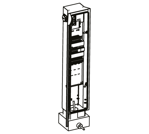
Floor version

Create a concrete base, placing a tube in the middle to run the cables. Ensure the base is level.

Once the concrete is dry, feed the power cable through the PVC tube.


Remove the charger base from its packaging.


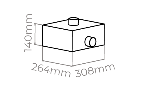
Take note of the charger’s base measurements.
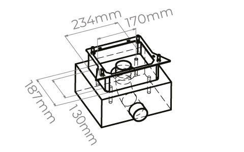

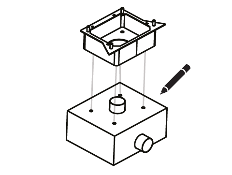
Place the charger base to mark the positions for the four fixing holes.

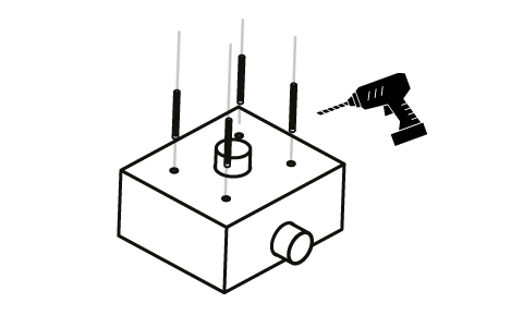
Drill at the marked positions and insert 100mm M10 threaded studs, leaving at least 20mm exposed, and secure them with chemical anchors.

Place the base and secure it with DIN 125 10.5 washers and DIN 934 M10 nuts. Ensure the base is level once fixed.
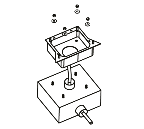

Place the equipment on the base and secure it with four DIN 125 10.5 washers and four DIN 934 M10 nuts. Finally, correctly connect the power cables to the existing terminals. Review the electrical connection section.
Wall version
Remove the wall-mounting brackets from the packaging.

Mark the drill holes for the wall mounting according to the indicated measurements.
In outdoor installations or those with potential humidity/water ingress, the conduit must be routed from below the charger to avoid direct exposure to rain. In this case, drilling should be done initially with a drill bit (never with a hole saw) and at a maximum distance of 5mm from the charger to prevent damage to the power board and its flat cable. The hole must be sealed, and all four plugs must be installed without exception.

Drill the marked points with an 8mm bit and secure the bracket using four No.8 L40 plugs and four DIN 7982 5.5×45 screws.
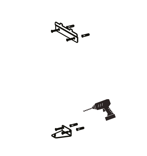
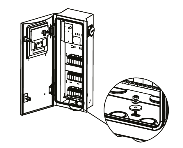
Attach the equipment brackets to the wall brackets.

Secure the equipment to the lower bracket using the 5×25 rubber washer, DIN 9021 5.3 washer, and DIN 934 M5 nut. Finally, correctly connect the power cables to the existing terminals. Review the electrical connection section.
Electrical installation
The power supply line must be connected to an existing installation that complies with local regulations. Adhere to the current national and international installation standards (e.g., IEC 60364-1 and IEC 603645-52). Install a circuit breaker and residual current device on the line that supplies the charging point. Additional protection may be added, respecting local regulations.
Circuit breaker
Protection against short circuits is ensured by the installation’s protective devices, which do not exceed 75,000 A2s in the event of a short circuit. When sizing the breaker, consider potential ambient temperature variations in the electrical panel. The selection of electrical protection current must correspond to the charger’s maximum output current. We recommend 1.25 times the circuit’s nominal current.
Residual current device sizing
This must be identified by a qualified technician. Each charging station must be connected to its own residual current device, and no other electrical circuit should be connected to this device. A super-immune Type A residual current device should be chosen (in accordance with national standards).
Surge protection sizing
If national legislation requires the installation of a surge protection device, it must be sized according to the charging station’s maximum current. It may be incorporated into the charging point by selecting the appropriate accessory.
Power supply line sizing
When sizing the installation, do so in accordance with regulations. Consider the temperatures the cable may experience, taking into account the characteristics of the load.
Electrical connection
It is recommended that the installed conduit extends 15 cm into the charger to prevent water from entering. The power supply is connected to the input switch located in the charger, which powers the entire charging device. Square ferrules are mandatory.
Electrical installation configuration
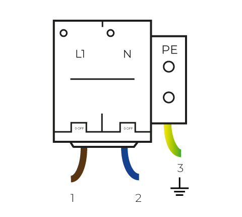
Single-phase Configuration: Connect the wires to the connection terminal according to the diagram: brown wire (1) to phase R (L1), blue wire (2) to neutral (N), and green/yellow wire (3) to earth or equipotential bonding (PE).
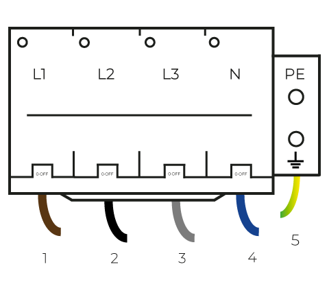
Three-phase Configuration: Connect the wires to the connection terminal according to the diagram: brown wire (1) to phase R (L1), black wire (2) to phase S (L2), grey wire (3) to phase T (L3), blue wire (4) to neutral (N), and green/yellow wire (1) to earth (PE).
Internet connection
Pole Pro can establish an Internet connection in various ways:
NOTE: You can change the WiFi configuration via the app. However, if you change it while currently connected via WiFi, the new configuration may be invalid, resulting in loss of Internet access.
How to charge with Pole Pro
Discover the initial charging process for our next-generation charger, from connecting the hose to interpreting the LED signals on the sockets. Learn how to enjoy efficient and advanced shared charging.


General features

e-Charger
Pole Pro

Colour
⚫ Black

Material
Vandal-resistant steel

Weight
55 kg

Display*
Yes
8” – 1.000 lumens
Mode
3 control PWM según ISO/IEC 61851-1
RFID reader
ISO/IEC 14443 A/MIFARE (In V2C Cloud models)

MID meter
In V2C Cloud models

Electrical protections per socket
Type A residual current device and 40A circuit breaker

Operating temperature
-25ºC a 70º
Storage temperature
-40ºC a 70º

Lighting according to charging status
Safety warnings

Risk of electric shock

Risk of residue projection
Risk of injury

Grounding required
Warning! Failure to follow safety instructions may result in death, personal injury, and equipment damage. V2C disclaims all liability for claims arising from non-compliance with these instructions.
Electrical hazard! The installation, initial start-up, and maintenance of the electric charging station must be carried out exclusively by competent and qualified technical personnel, fully responsible for compliance with installation regulations and existing standards.
V2C carries the CE mark. V2C applies the corresponding declarations of conformity.
V2C complies with the ROHS directive (2011/65/EC). V2C applies the corresponding declarations of conformity.

Electrical and electronic equipment, as well as their accessories, must be disposed of separately from household waste.
Do you need technical support?
Resolve your issue instantly through our AI Chat. If it is not resolved, submit a request via the Technical Support Centre and we will contact you as soon as possible to provide the best solution.