Installation manual for Denka
For the proper functioning of an e-Charger, it is crucial to follow all the instructions provided in its installation manual. It is essential to understand all potential risks, follow every necessary step, and use the appropriate tools to ensure a safe and successful installation.
This installation manual compiles all the information in detail to guide you through the entire installation process of our Denka e-Charger. Within this manual, you will find all the guidance you need to carry out a professional installation.
This manual is subject to changes in the information without prior notice. The images included are for illustrative purposes and may not exactly match the actual products.
Tools required for installation

Drill

Hammer

Screwdriver

Tape measure

Spirit level and pencil
Accessories included with the charger

6x
10x50mm N+Plus Nylon Plug
4x
Screws (hexagonal head wood screws) DIN 571 8x50mm CuZn
1x
Security screw key
1x
Cable reel basket (part for placing the hose)
Steps to follow for the e-Charger installation

Denka is anchored to the wall using a plate. Take into account the dimensions of the plate in relation to the charger.


Mark the drilling points on the plate that is anchored to the wall.


Drill over the marked points with a 10mm drill bit and insert the wall plugs.


Place the plate on the wall using the zinc-plated hexagonal head screws ø8mmx50mm with wide-winged washers ø9mm and the corresponding wall plugs.


Attach the charger to the plate screwed to the wall through the rear slots.


Secure the charger with two lateral screws with countersunk heads ISO 7380 M5x40mm.


Open the charger cover by removing the security screws with countersunk heads ISO 7380 M5x20mm.


Place the cable tie on the wall to pass the incoming hose through it. Leave it unfixed while the connections are being made. It is recommended to use a heavy-duty omega-type clamp for walls.


Insert the incoming hose and the Ethernet cable, securing them with the cable gland. Proceed with the electrical connection (see next section).


Once the hose is in place, tighten the cable tie to secure its position.


Install the hose support at the recommended distance using zinc-plated hexagonal head screws M4x40mm (x3) and nylon wall plugs ø6mmx40mm (x3).

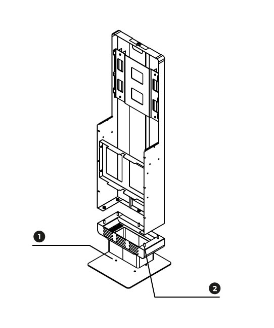
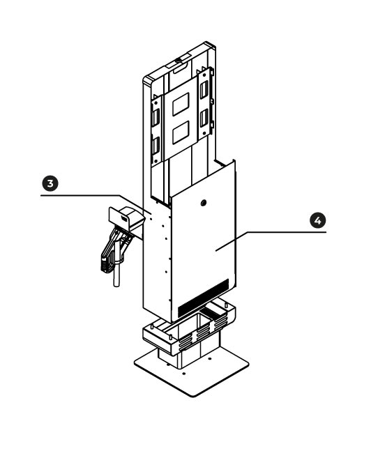
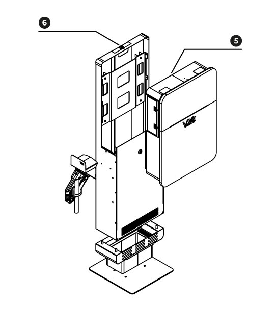
Steps to follow for assembling the pedestal
IMPORTANT: The pedestal is watertight, so nothing can be placed inside.
First of all, locate the pedestal parts and the charger.

Después, sigue los pasos para su montaje:
First, screw part 2 to part 1. Next, fit part 3 into part 2 and secure it with washers and nuts.
Then, screw part 4 to part 3 and slide part 5 down to fit it in place.
Finally, screw part 6 onto part 3 and secure part 6.
Electrical installation
Three-phase installation: brown cable (1) to phase R (L1), black cable (2) to phase S (L2), grey cable (3) to phase T (L3), blue cable (4) to neutral (N), and green/yellow cable (5) to the earth terminal (PE).

Ethernet connection
To make the Ethernet connection, the corresponding cable should be connected to the RJ45 connector located next to the electrical connection.

4G connection
The connection is made through a SIM card from any of the available network providers. The SIM card should have its PIN number removed beforehand. Insert the SIM card into the designated slot on the control board.

Maintenance
To keep the charger in optimal condition, it is necessary to replace the filters. They have an approximate lifespan of one year. They are G2 type filters, measuring 78x254mm, and are supplied by V2C.


General specifications
e-Charger
Denka
Power
20kW / 40kW

Color
⚪ White and grey

Material
Aluminum and synthetic coating

Weight
50 kg

Cable and connector type
Straight / CCS Combo Type 2

Cable length
4,5m
Efficiency
≥ 95%

Lighting based on charging status and percentage

Operating temperature
-30ºC a 55º
Dynamic power control
Via external meter

Electrical protections
Mandatory for outdoor installation

RFID Reader
ISO/IEC 14443 A/MIFARE

Payment terminal
Optional
Safety warnings

Risk of electric shock

Debris projection
Risk of injury
Caution

Grounding required
Do not use damaged connectors
Do not remove information or warning symbols
Warning! Failure to follow safety instructions may result in death, personal injury, or damage to the equipment. V2C disclaims any responsibility for liabilities arising from such non-compliance.
Electric danger! The installation, initial startup, and maintenance of the electric charging station must be carried out exclusively by qualified and competent technical personnel, who are fully responsible for complying with the installation provisions and existing standards.
This e-Charger in mode 4 is classified under section 5 of UNE-EN 61851-1 as an EV power system connected to an AC supply network. The EV power system is either wired or permanently connected. Its use is recommended for public roads and public-private spaces, and it can be used in both restricted and unrestricted access areas. Installation can be carried out on a wall or pedestal, and must be done on a flat surface. It is protected against electric shock to Class II standards.
The power supply line must be connected to an existing installation and comply with national and international regulations. Each charging station should be connected to its own residual current circuit breaker (RCCB) with a residual operating current not exceeding 30mA of type A. The charger must be connected to a three-phase network capable of providing 40kW. Additional protective elements may be added. The installation sizing should be done according to the current national regulations.
V2C carries the CE mark. V2C applies the corresponding conformity declarations.
V2C complies with the RoHS directive (2011/65/EC). V2C applies the corresponding conformity declarations.

Electrical and electronic equipment, as well as their accessories, must be disposed of separately from household waste.
Do you need technical support?
Resolve your issue instantly through our AI Chat. If it is not resolved, submit a request via the Technical Support Centre and we will contact you as soon as possible to provide the best solution.