
Trydan single-line diagram with protections
The single-line diagram of the Trydan electric charger provides a clear and detailed visual representation of the arrangement and connection of all the electrical components that make up this advanced charging device.
This single-line diagram is a fundamental tool for understanding the electrical architecture of the Trydan charger. It facilitates the identification of each component and its function within the electrical system, which is crucial for maintenance, repair, and diagnosis of potential issues. With this visual representation, engineers and technicians can easily perform preventive maintenance tasks, as well as identify and troubleshoot any issues that may arise during the operation of the Trydan electric charger.
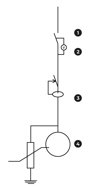
Circuit breaker(IGA) + transient and permanent overvoltages
Combined with Differential (below)
2P
C Curve
In: 32 A
Icu: 6 kA
Type II
Imax=5kA
EN61643
Differential single-phase
In: 40 A
30 mA
instant
Type A ‘SI’
Recharging Point
7,36kW
Do you need technical support?
Resolve your issue instantly through our AI Chat. If it is not resolved, submit a request via the Technical Support Centre and we will contact you as soon as possible to provide the best solution.