
Configuration of MID meters
It is called a MID meter because it is certified under the MID regulation (European Directive 2014/32/EU, Measuring Instruments Directive). This certification works like a calibration: it guarantees that every kWh the meter shows is really the kWh the car has received. These meters also leave the factory already configured.
The Trydan’s internal MID meter only measures the energy the charger delivers to the car. It does not measure what is consumed from the grid or what is exported from solar production, and it is not used for dynamic power control. That requires a compatible external meter, which is a separate device.
In this manual, you will find step by step how to configure the Modbus RTU communication address for the two models of MID meter: single-phase and three-phase. For the wiring of the meter within the installation, refer to the guide on wired meters.
The installation and configuration must be carried out by qualified and competent technical personnel, fully responsible for complying with the installation provisions and existing regulations.
Before you start
Note 1: the images in this guide are a visual representation to show you the steps for the setup. The correct addresses to enter are these:
- Internal MID meter of the Trydan: address 11. If there are multiple Trydan units in series or connected to the same bus, each meter needs a different address to avoid conflicts: 11, 12, 13…
- MID meter used for dynamic control: direction 1.
Note 2: the certified MID meters come factory-configured by default, so this guide is just a visual aid. Do not confuse them with the external Trydan meters for dynamic control. The guide can help you review their settings, but those meters always have address 1 and have different references. You can check the compatible meters on our website: v2charge.com.
Single-phase MID meter
Reference: RS485MID · Operation: Modbus address programming
This model is programmed with a single key,  . Follow the steps in the indicated order, using the images on the device’s screen as a guide.

Connect the brown wire, phase (L), to input 1 and the blue wire, neutral (N), to input 2. Then, connect the meter to the electrical network.
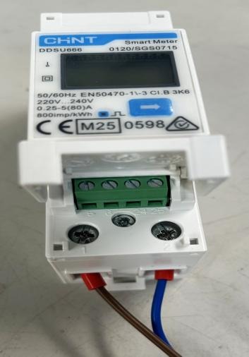
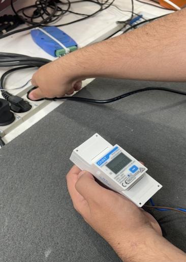

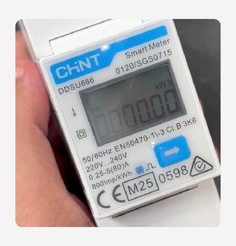
Wait for the screen to display 0000.00 before continuing with the setup.
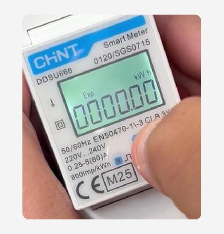

With the screen at zero, press and hold the key for about 5 seconds. The screen will cycle through the Modbus communication parameters of the equipment: protocol, address, baud rate, and frame format.
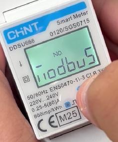
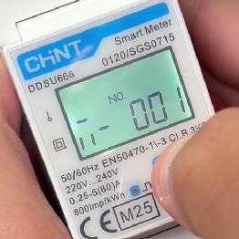
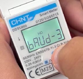
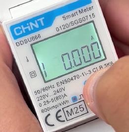
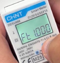
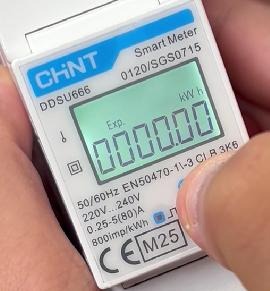
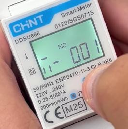
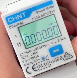

When the frame format screen (8n1) appears, release the key and wait for the current Modbus address of the device to be displayed.
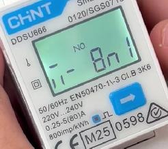
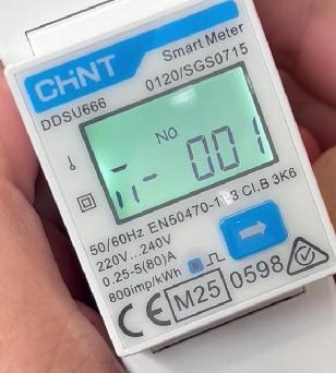

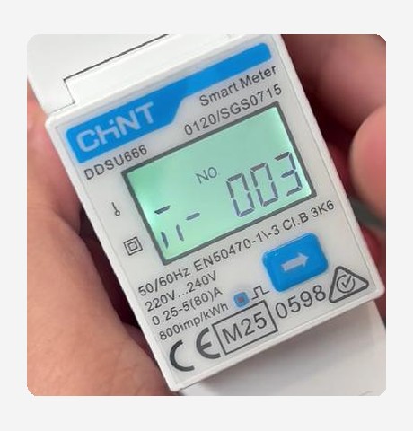
Press the key until the device number that corresponds to your installation appears. In this example, the selected address is 003.

Without pressing any keys, wait until the screen returns to the normal consumption reading (kWh).

Disconnect the current meter. The setup is complete.
Three-phase MID meter
Reference: EM340DINAV23XS1PFB · Operation: change of Modbus communication direction
To access the configuration menu of this model, it is necessary to enter the user password. Below we show you, with a practical example, how to do it and how to modify the communication address.
Device Keys
Change screen / increase value Confirm / move cursor
 Exit / save
Default user password: 701
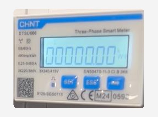
Connect the equipment and the meters. Before starting, the screen should display 00000.00.
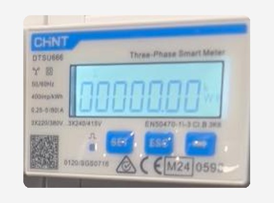
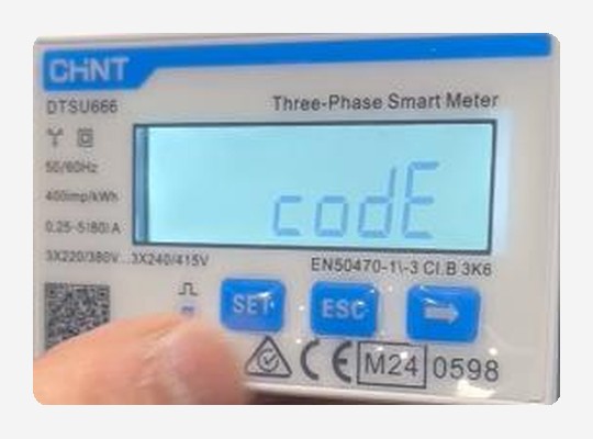
Press the key . The screen will display codE.
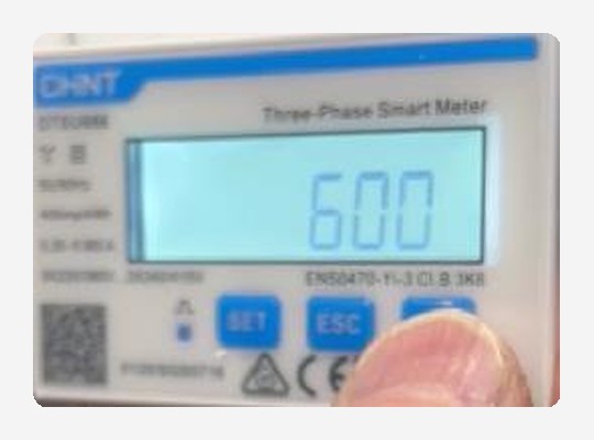
Press again. 600 will appear, with the last digit blinking.
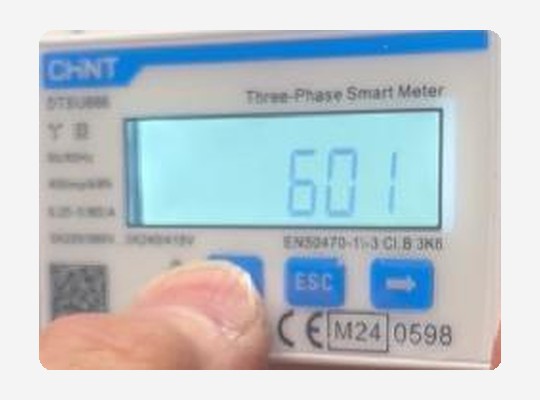
Press to change the last digit from 0 to 1. The screen will display 601.
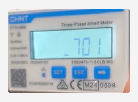
Press twice to move the cursor to the first digit and press to change the 6 to a 7. The screen will display 701, the access password.
Press to confirm the password and access the programming interface. The screen will change to Ct (configuration parameters).
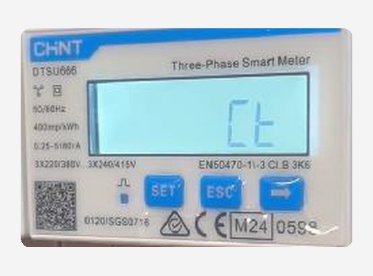
Press . The screen will change to Pt.
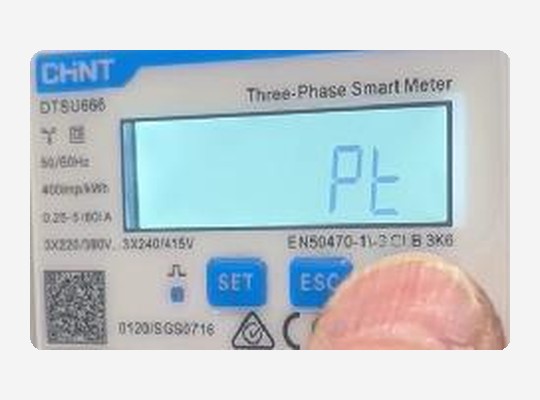

Press again. The screen will change to Prot (communication protocol).
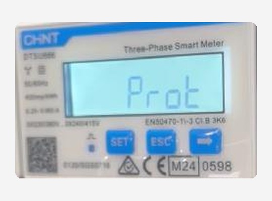

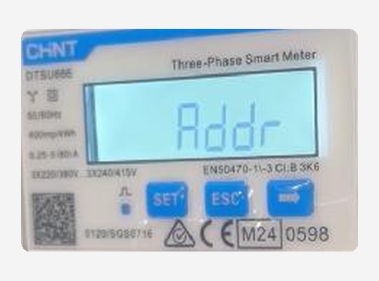
Press again . The screen will change to Addr (Modbus communication address).
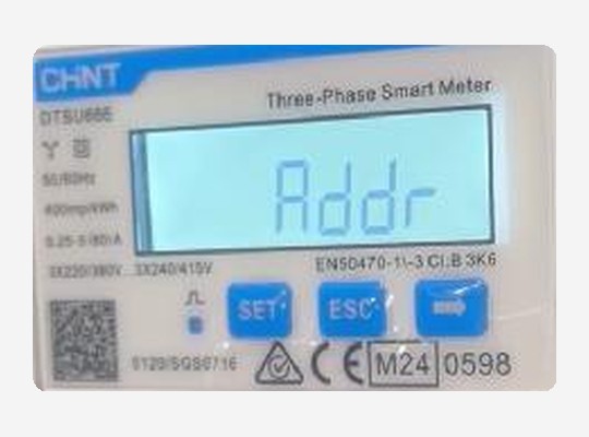

Press to edit the address. The screen will display the current address, in this example 1.
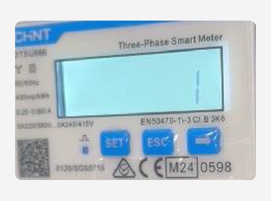

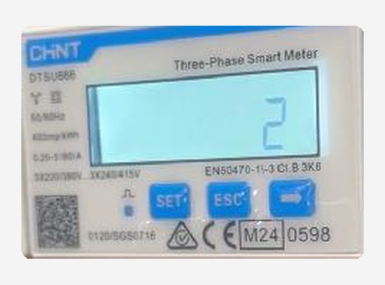
Press until you reach the address corresponding to your installation. In this example, 2.

Press . The screen will return to Addr, confirming the new address.

Press again . The screen will return to the normal consumption reading. The meter is programmed.
Sequence Summary
| Action | Key | Screen |
|---|---|---|
| Enter programming | | codE |
| Show password | | 600 |
| Increase last digit | | 601 |
| Move cursor to first digit | | 6_1 → _01 |
| Increase first digit | | 701 |
| Confirm password | | Ct |
| Go to communication address | ×3 | Pt → Prot → Addr |
| Edit address | | Current address |
| Change address | | New address |
| Confirm address | | Addr |
| Exit | | Normal reading |
To configure other parameters of the meter, the same keys are used, following this same sequence.
Important
The Modbus address assigned to the meter must match the one configured in the e-Charger or in the system it will be integrated with. If you have any questions during the setup, please contact our Technical Support.
Do you need technical support?
Resolve your issue instantly through our AI Chat. If it is not resolved, generate a request in the Technical Support Center and we will contact you as soon as possible to provide you with the best solution.