
Dynamic power control for one or multiple e-Chargers

The most common way to manage energy through power control involves integrating a home, business, or facility with one or multiple additional e-Chargers.
Dynamic power control is an advanced energy management feature that detects real-time energy usage in your home or business to charge your electric vehicle at maximum power, thus preventing overloads. By using devices capable of measuring consumption, the e-Charger can monitor, in real-time, the power demanded (or energy generated if you have photovoltaic energy) and make use of it accordingly. This means it can balance the charger’s power with the excess power from the home or business, or from the photovoltaic installation, if available.
Which e-Charger do you use for dynamic power control?
Dynamic power control with Trydan or Trydan Pro
What are the available methods for performing dynamic power control with Trydan or Trydan Pro?
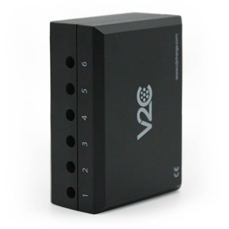
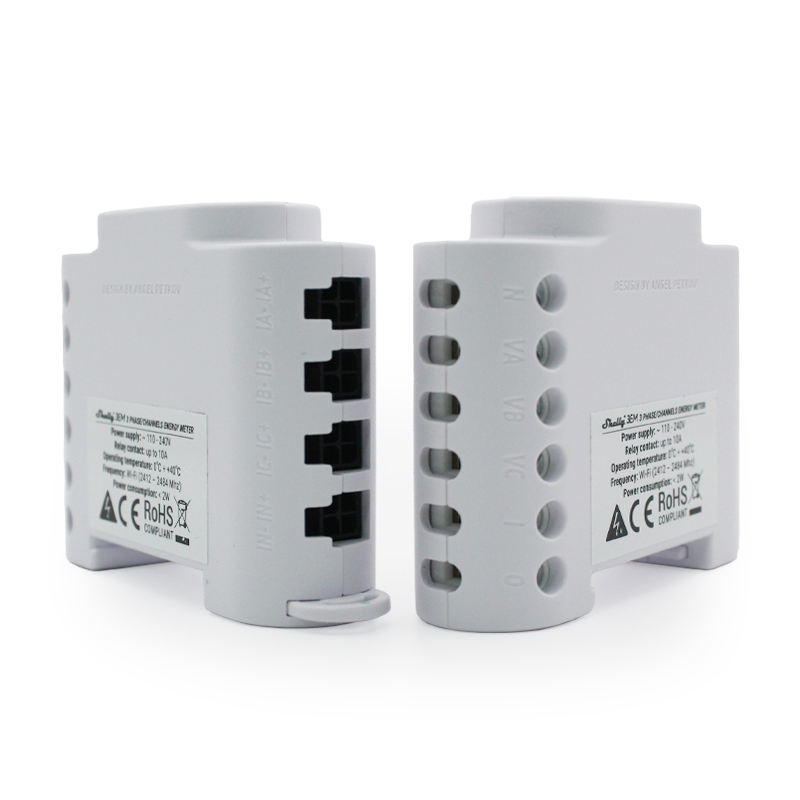
V2C ControlBox (V2C 2.0 meter)
The V2C ControlBox device is convenient, intuitive, and easy to install. It is included when purchasing Trydan or Trydan Pro, along with a clamp that connects to the main supply line of the property (covering home consumption + electric vehicle).
With a single device, it offers readings of up to six channels, allowing measurements in standard installations, whether single-phase or three-phase, even if photovoltaic energy is available.
IMPORTANT NOTE: In photovoltaic installations with storage batteries, do not use the V2C ControlBox. Instead, use one of the WiFi or wired meters specified on this same page.
There is an earlier version, V2C 1.0, which is no longer marketed, although it may still be found in some installations.
WiFi meters
This is an alternative when running an Ethernet cable from the e-Charger to the V2C ControlBox is not feasible. The WiFi meter and the charger must be connected to the same WiFi signal. You can choose either Shelly or Wibeee, two of the most well-known WiFi meters.
If you have photovoltaic energy and your inverter is connected to a secondary panel (or the charger is directly connected to the meter) and it is not possible to measure its output, this is the appropriate meter. It can measure the direction of current flow, enabling the use of all charging modes offered by Trydan due to its bidirectional reading capability.
Wired meters
Another option is wired meters, including models such as Carlo Gavazzi, Chint, Eastron, or Phoenix Contact.
These can be used when you have photovoltaic energy but cannot install the V2C ControlBox (due to the inverter being connected to a different panel than the charger) and WiFi connection is also unavailable (if you have a suitable WiFi signal, a WiFi meter is preferable).
These meters do not allow solar generation to be viewed on V2C Cloud; however, all solar energy operation modes function correctly.
Direct connection with the inverter
Our Trydan and Trydan Pro e-Chargers, industry pioneers, are the first chargers to enable direct connection with a solar inverter, enhancing system efficiency and simplifying installation and maintenance.
This type of connection can be established via WiFi, Ethernet, or RS485 with inverters such as Huawei, Kostal (Piko, KSEM, Plenticore), Goodwe, Solis, Greenheiss, SAJ, Fronius, Victron, SolarEdge, Ingeteam, etc. Discover how to connect your e-Charger model to photovoltaic energy.
A direct connection is essential when the inverter is compatible with Trydan to obtain accurate battery readings.

Via MQTT protocol
Additionally, measurements can be performed using the MQTT protocol, which enables efficient communication between the e-Charger and other devices, allowing precise and swift control of the electric vehicle charging process.
The installation must be carried out by competent and qualified technical personnel who are fully responsible for compliance with installation provisions and existing regulations.

TRYDAN ONLINE COURSE
Discover the free online training that will give you in-depth knowledge of the most in-demand charger on the market.
Installation diagrams
Below are the valid diagrams to identify the correct arrangement of the various elements that make up the dynamic power control installation.
SINGLE-PHASE INSTALLATION DIAGRAMS
V2C ControlBox (V2C 2.0 meter)
Single-phase installation diagram + V2C ControlBox

It presents one of the most common situations that an installer may encounter. In this scenario, the current clamp connected to jack 1 of the meter must encircle the main supply cable (upstream, meaning before it reaches and is positioned above the main panel – including the main supply and the charger).
WiFi meters
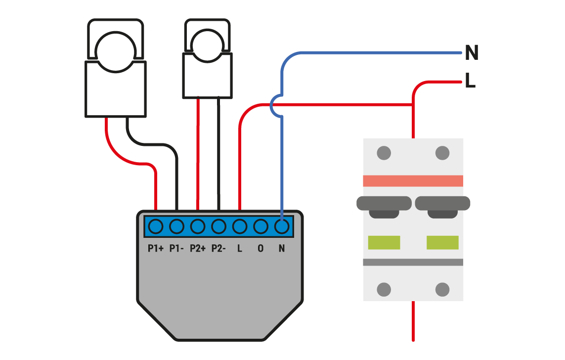
Single-phase installation diagram + Shelly meter (Example)

This diagram should be followed when it is not possible to run an Ethernet cable from the meter to the charger, as this will establish wireless communication between the device and the e-Charger. It is important that both the Shelly meter and the charger are connected to the same WiFi network as the user (not the one generated by the charger itself).
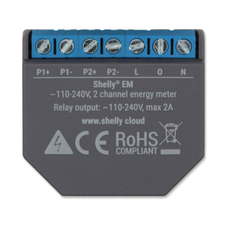
How to install the Shelly meter?
The Shelly meter diagram can be used as a reference for all types of WiFi meters. The installation of the Shelly meter will differ for single-phase and three-phase installations, as the device is different in each case. This type of meter requires a power supply.
Legend
N Neutral input (110-230V AC)
L Line input (110-230V AC)
P1+ Positive connection for current clamp 1
P1- Negative connection for current clamp 1
P2+ Positive connection for current clamp 2
P2- Negative connection for current clamp 2
Wired meter
Single-phase installation diagram + Wired meter (Example)

This meter will be used when installation with the V2C Control Box is not possible, and there is also no WiFi signal available.
How to install wired meters
If it is necessary to use a wired meter such as Eastron, Carlo Gavazzi, Phoenix Contact, Chint, etc., the connection will be made as shown in the diagram below*:


Steps for installation
- Connect the neutral phase cable to terminal 3 and the phase cable to terminal 4.
- Connect the white cable from the current clamp to terminal 1 and the black cable to terminal 2.
- Connect the meter to the control board of the charger using a UTP cable. Make the connection at the meter using only two cables: connect pin 4 to terminal 9, and pin 5 to terminal 10.
NOTE: It is important that the loose UTP wires are insulated and do not make contact with each other.
IMPORTANT NOTE: Wired meters used for the operation of dynamic power control must be used exclusively for this purpose. The installation of these meters must follow the electrical diagrams or instructions as outlined in the manual for each device.**
* Some meters indicate that the communication terminal B is positive (B+) and terminal A is negative (A-). To connect correctly, you should connect pin 4 of the RJ-45 connector from Trydan to terminal A- and pin 5 of the RJ-45 connector from Trydan to terminal B+ of the meter.
** If you already have a meter, you must ensure that it is configured with the ‘Modbus’ protocol type, a baud rate of ‘9600’, and a communication address of ‘1’.
THREE-PHASE INSTALLATION DIAGRAM
V2C ControlBox (V2C 2.0 Meter)
Three-phase installation diagram + V2C ControlBox

This setup addresses one of the most common scenarios that an installer may encounter.
The current clamp is positioned on jacks 1, 2, and 3, surrounding the cables from the main supply.
** If the charger is single-phase, it will only be powered by phase 1 from its panel.
WiFi meters
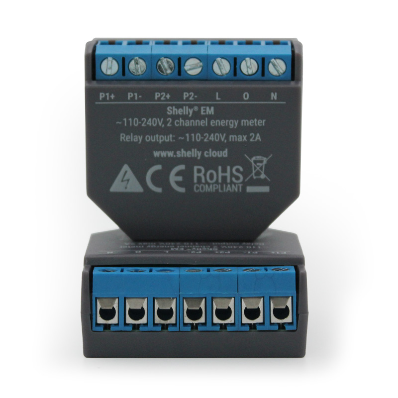
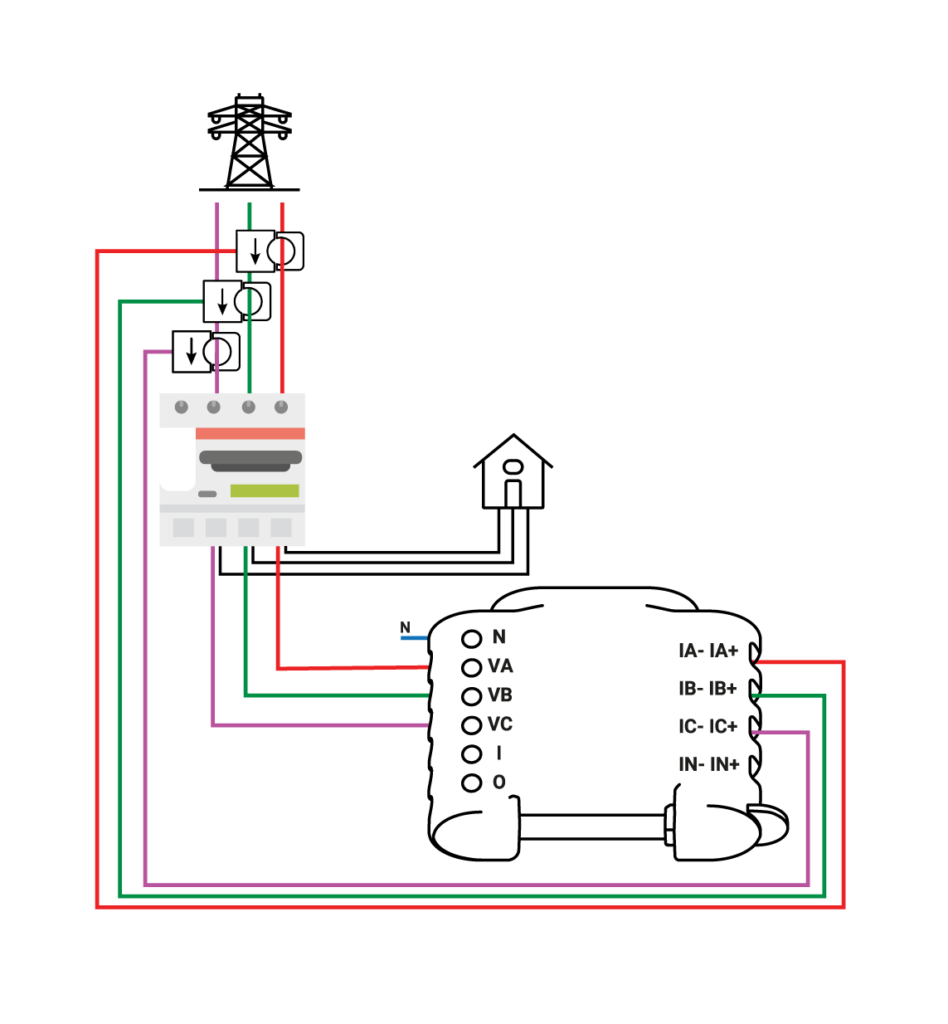
How to install the Shelly meter in three-phase installations?
The installation of the Shelly meter will vary depending on whether it is a single-phase or three-phase installation, as the device used in each case is different. Additionally, these meters need to be connected to the electrical supply for operation.
Legend
N – Neutral input (110 – 230V AC);
VA – Line input Phase A (110-230V AC);
VB – Line input Phase B (110-230V AC);
VC – Line input Phase C (110-230V AC);
IA: IA+ – Input for Phase A current clamp
IB: IB+ – Input for Phase B current clamp
IC: IC+ – Input for Phase C current clamp
IN: IN+ – Input for neutral current transformer
Wired meters
How to install wired meters in three-phase installations?
Just as in single-phase wired meters (Eastron, Carlo Gavazzi, Phoenix Contact, Chint, etc.), the connections will be made as shown in the diagram below*:

Steps for installation
- The equipment has 3 current clamps. Connect S2 (black) and S1 (white) to their respective ports. The phase number is indicated at the bottom, being 3, 2, and 1.
- Supply the neutral, phases 3, 2, and 1 to the terminals at the bottom.
It is mandatory to power the LA with phase number 1 and the NA with the neutral to provide power to the meter. - Connect the meter to the control panel of the charger using a UTP cable. Make the connection at the meter using only two cables: connect pin 4 to terminal B- and pin 5 to terminal A+.
NOTE: It is important that the loose UTP wires are insulated and do not make contact with each other.
IMPORTANT NOTE: Wired meters used for the operation of dynamic power control must be used exclusively for this purpose. The installation of these meters must follow the electrical diagrams or instructions as outlined in the manual for each device.*
* Some meters indicate that the communication terminal B is positive (B+) and terminal A is negative (A-). To connect correctly, you should connect pin 4 of the RJ-45 connector from Trydan to terminal A- and pin 5 of the RJ-45 connector from Trydan to terminal B+ of the meter.
** If you already have a meter, you must ensure that it is configured with the ‘Modbus’ protocol type, a baud rate of ‘9600’, and a communication address of ‘1’.
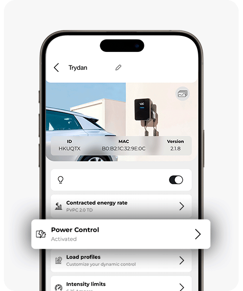
Steps to follow for configuration and activation
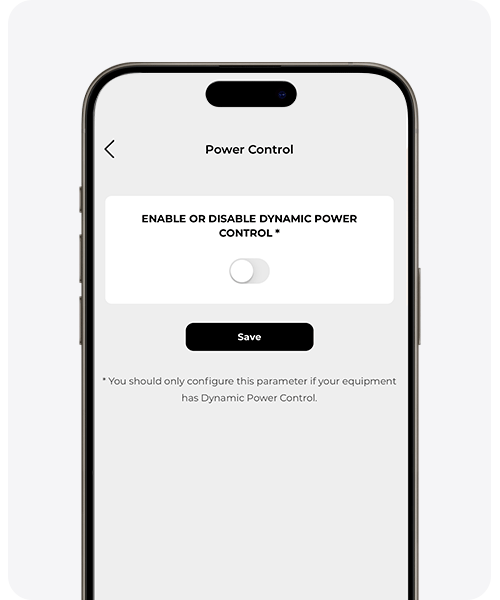
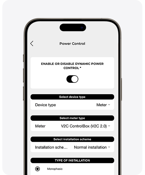
Once the installation of the relevant meter has been completed, it is essential to optimally configure the dynamic power control. Without this step, the e-Charger will not automatically and dynamically allocate any surplus energy from the home or business to the electric vehicle charging.
This configuration can be carried out via Bluetooth or WiFi (if available) and accessed through the V2C Cloud app or on a computer at www.v2c.cloud, using your user credentials and password. In both cases, follow the instructions provided in the image.
* The meter installation must be carried out by a professional. The V2C Control Box will be used by default if no alternative is available. There are various versions of meters; therefore, it is crucial to select the appropriate meter, considering the existing installation type, and to save the configuration.
Custom power control configuration
Customising power control through charging profiles is vital for improving efficient energy management.
By adapting the system to your specific needs, you not only maximise the efficient use of energy but also gain complete control over the charging profiles, allowing you to adjust timings, intensity, and charging mode. This results in savings on your energy bills, optimising every resource and elevating energy efficiency standards to a new level.
If an error occurs when activating dynamic power control at the Trydan or Trydan Pro charging point, a code corresponding to that error will appear on the charger’s display. Refer to the connection error diagnostics to ensure proper use of dynamic power control.
Dynamic power control with Pole Pro
In what ways can dynamic power control be implemented with Pole Pro?
Pole Pro meter
The energy meter provided by V2C uses open toroidal clamps. For optimal operation, this meter must be installed at the main supply of the entire installation. This allows for the measurement of consumption from both the charging points and the rest of the installation, including the possibility of integrating a photovoltaic system that injects energy.
If you purchase the meter directly from V2C, please note that it comes preconfigured for use. Additionally, you can choose clamps rated at 250, 400, or 600 amperes, depending on the specific needs of your installation.

IMPORTANT NOTE: Wired meters used for the operation of dynamic power control must be used exclusively for this purpose. The installation of these meters must follow the electrical diagrams or instructions as outlined in the manual for each device.
If you already have a meter, ensure that it is configured with the protocol type ‘Modbus’, a baud rate of ‘9600’, and a communication address of ‘1’.

To carry out the installation of the meter, follow these steps:
- Power the meter with the neutral and the corresponding phases at the upper terminals.
- Connect the meter to the e-Charger using two RS485 wires:
Meter model EM330 or EM340 (standard Pole Pro Meter)
Charger connector B- → meter terminal 12 (A-).
Charger connector A → meter terminal 11 (B+).
Meter model EM530 or EM540
Charger connector B- → meter terminal 9 (A-).
Charger connector A → meter terminal 8 (B+).
NOTE: To establish the Modbus connection, any shielded cable designed for this purpose, which contains a twisted pair of wires, can be used. However, a convenient option is to use UTP cable due to its practicality.
If you choose to use UTP cable, we recommend using a shielded Category 6 cable and employing the same twisted pair to minimise noise as much as possible. Additionally, it is important that the loose UTP wires are insulated (properly crimped) and do not make contact with each other.
Custom power control configuration
Adapting power control using charging profiles is crucial for more efficient energy management.
By personalising the system to your specific needs, you not only ensure a more efficient use of energy but also gain complete control over the charging profiles, allowing you to adjust timings, intensity, and charging modes. This translates into savings on your bills, maximising each resource and elevating energy efficiency standards to a higher level.
Do you need technical support?
Resolve your issue instantly through our AI Chat. If it is not resolved, submit a request via the Technical Support Centre and we will contact you as soon as possible to provide the best solution.