
Leak Detector Installation Diagram
To carry out the installation, the connector of the leak detector must be placed in the LEAK DETECTOR port of each power board. Subsequently, the cables coming from the power board should be routed to the charging hose through the coil, depending on the type of installation (single-phase or three-phase).
Single-phase installation
Pass the Neutral (blue) and Phase 1 (brown) wires (that go from the power board to the cable) through the coil, always leaving the Earth wire (yellow and green) outside.
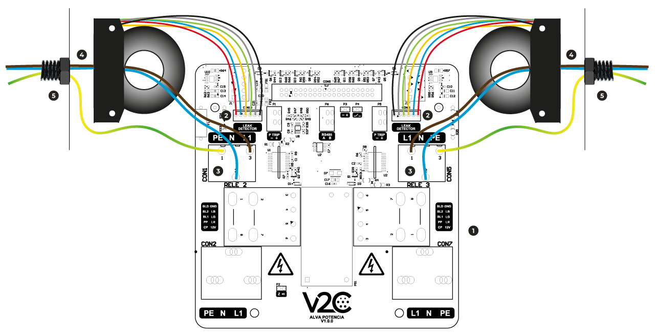

Power plate

Leak detection connector

Coil connector

Coil

Charging cable
Three-phase installation
Pass the Neutral (blue), Phase 1 (brown), Phase 2 (black), and Phase 3 (gray) wires (that go from the power board to the cable) through the coil, always leaving the Earth wire (yellow and green) outside.
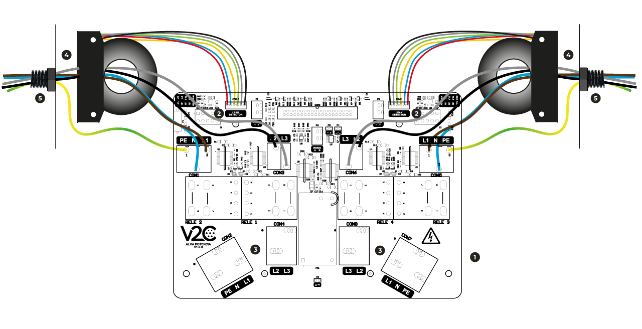
Power plate
Leak detection connector
Coil connector
Coil
Charging cable
Do you need technical support?
Resolve your issue instantly through our AI Chat. If it is not resolved, generate a request in the Technical Support Center and we will contact you as soon as possible to provide you with the best solution.