

Electrical protections
The Alva charger includes a series of electrical protections designed to ensure the safety of the installation and the user during charging. On this page, you will find their location within the equipment, how they are connected, and their operation. Before handling these protections, make sure to disconnect the power supply of the charger and always follow the current installation regulations.
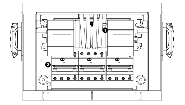

Ground terminal

Electrical protections
The handling of the equipment must be carried out by competent and qualified technical personnel, fully responsible for complying with the installation provisions and existing standards.
Before handling the charger, disconnect the power and use the appropriate tools. If the equipment is used or modified outside of what is specified by the manufacturer, safety may be compromised, releasing all liability for improper use. The interior of the equipment should only be handled by our technical service personnel.
Connection
Single-phase
MINI-PT-TDA
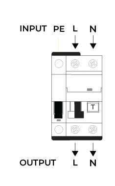
For the proper functioning of the equipment, the Phases must be connected to the terminals ‘L’ and the neutral to the terminal ‘N’.
DO NOT INSTALL ON LINES WITHOUT NEUTRAL (N) AND WITHOUT GROUND (PE).
If one of the Phases (L) is incorrectly connected in place of the Neutral (N) and power is supplied to the equipment, the warning window will flash quickly in green indicating that there is a connection error.
Diagram
Single-phase
MINI-PT-TDA
Operation
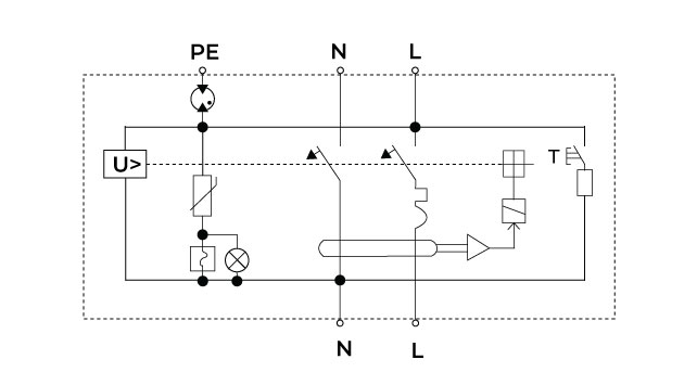
The equipment continuously measures the voltage in the installation and detects any increase above 10% of the nominal voltage. In case of detecting such an anomaly, it acts on the IGA (Automatic General Switch), disconnecting the voltage in the installation. The response time will depend on the level of overvoltage detected (according to the specifications of the UNE-EN50550/63052 IEC-63052:2019 standard).
The device will be operational again once it is manually reset, as long as the voltage is within its nominal values.
In the event of a transient overvoltage, the equipment absorbs it, diverting it to ground, thus preventing any damage to the devices connected to the network. The warning window will remain continuously illuminated in green.
If, due to a transient overvoltage, the protection becomes inoperative, it will display the warning window in red. In this case, the protective module will have been rendered unusable and must be replaced with another one.
When wiring the equipment, if one of the phases (L) is incorrectly connected in the place of the neutral (N) and we power on the equipment, the warning window will blink rapidly in green indicating that there is a connection error. If the equipment is properly connected and functioning correctly, the warning window will blink slowly in green.
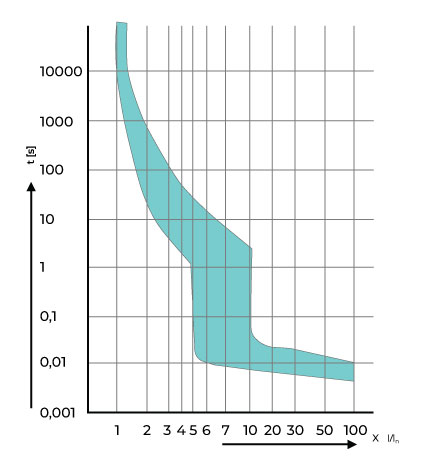
Trigger curve
MINI-PT-TDA specifications
General
| Nominal Voltage Un | 240 VAC |
| Frequency | 50-60 Hz |
| Maximum Terminal Section | 25mm2 |
| Nominal Sensitivity ln | 30 mA |
| Number of Poles | 1P + N |
| Environmental Margins | -20º +70º / 80% H.R. |
| Protection | IP20 |
| Mounting | DIN Rail 35 |
| Number of DIN Modules | 3 |
| Directives | 2014-35-EU (LVD) 2014-30-EU (EMC) 2014-65-EU (RoHS) |
Permanents
| Trip Voltage Response Time for Overvoltage | According to standard UNE-EN50550/63052 IEC-63052:2019 |
Transitional
| Maximum current lmax | 12.5 kA ; 8/20 |
| Nominal current In | 6 kA |
| Protection level Up | ≤1.5kV |
| Type | 2 |
IGA
| Nominal current | 40 A |
| Curve | C |
| Breaking capacity | 10 kA |
DIF
| Nominal sensitivity In | 30 mA |
| Type | A |

Do you want to check the complete internal breakdown? Access the Alva breakdown page to see all its components in detail.
Do you need technical support?
Resolve your issue instantly through our AI Chat. If it is not resolved, generate a request in the Technical Support Center and we will contact you as soon as possible to provide you with the best solution.