

Installation Manual for Alva
The perfect installation of an e-Charger is the essential step for its proper functioning. It is crucial to understand the risks, the essential steps, and the necessary tools in order to carry out a safe and successful installation.
This manual contains all the detailed information that will guide you through the installation process of our e-Charger Alva. You will find everything you need to know to carry out these tasks with the utmost precision.

The manual may be updated and present changes in the information without prior notice. All images shown in this installation manual are representative and may differ from the actual final products.

You can also download the complete installation manual in PDF.
Essential tools for installation

Drill

Screwdriver

Level and pencil
Accessories included with the charger

1x
Mounting bracket

4x
Taco N8 L40 (Ø8 x 40mm)

4x
DIN screw 7982, 5.5 x 45mm

4x
Key for the equipment locks

2x
DIN Washer 9021 M6
Wall mounting and wiring
Alva allows for two installation variants on the wall and wiring depending on whether the equipment includes integrated electrical protections or not. The first 4 steps are common to both variants.
Do you want to know in detail the different elements that make up the equipment before handling it? Check the internal breakdown.
Installation of the version with integrated electrical protections
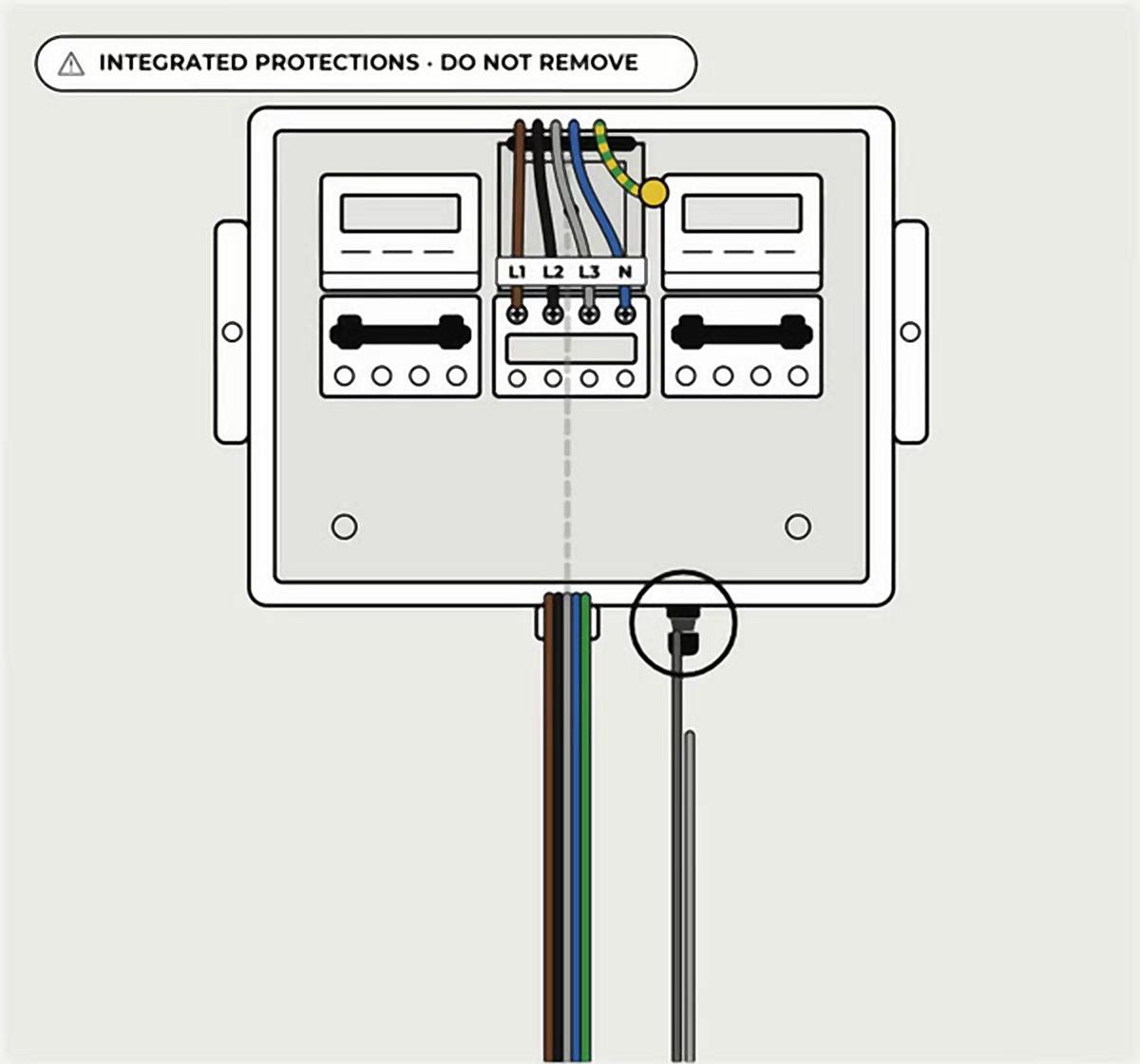
Very important: the protections come factory-installed, in a single piece. Do not remove it · Do not move it · Do not manipulate the lower supports.

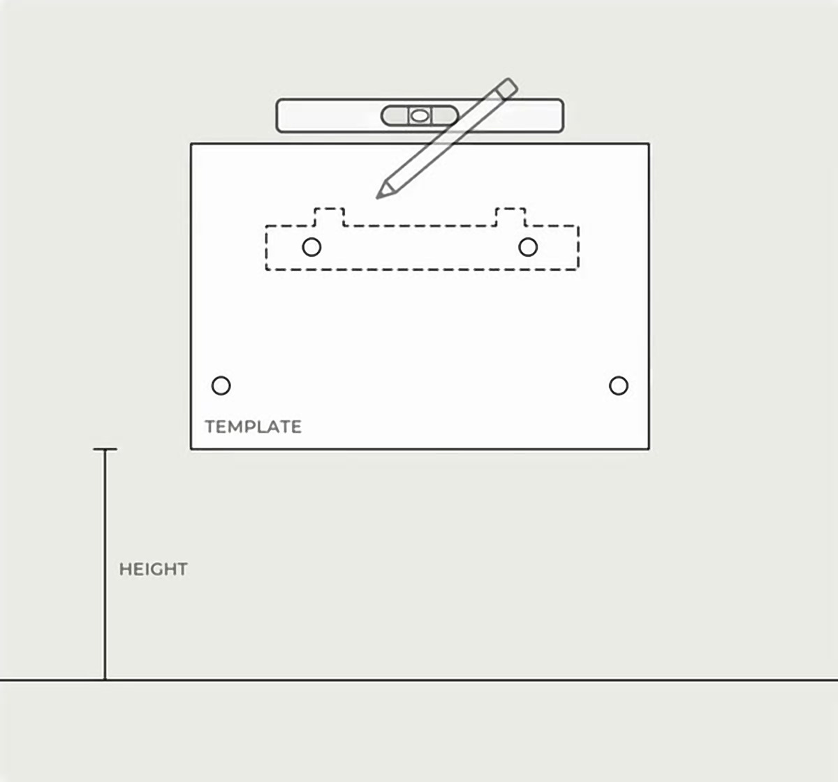
Mark the drill holes. Place the template at the desired height, level it, and mark the four drill holes.

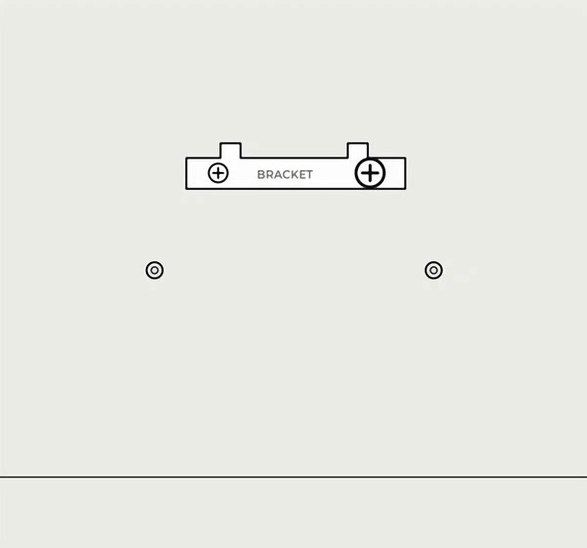
Fix the bracket. Drill the four marks, insert the plugs, and screw the bracket into the two upper holes.

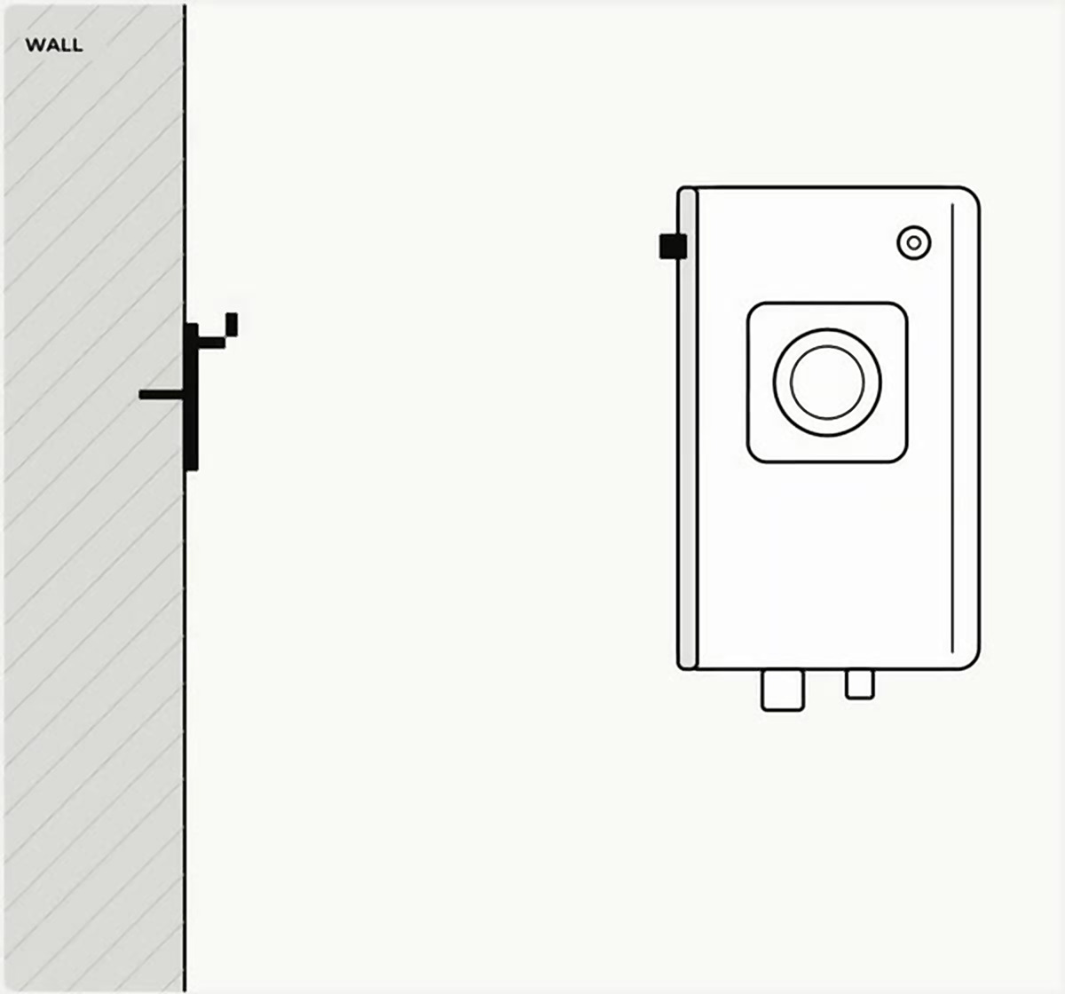
Hang the equipment. Bring the equipment close to the wall and fit it into the bracket.

Secure the bottom. Open the door and, with a long screwdriver, secure the bottom with the screws from the box.
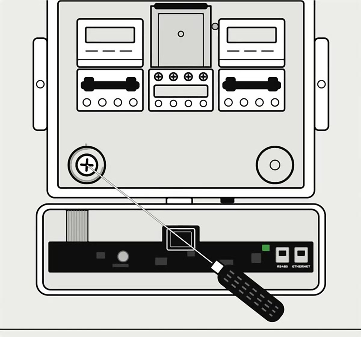

Pass the power cables. Through the cable pass and with the help of a guide: one by one or together, depending on the cable size. Do not attempt to remove the protections.
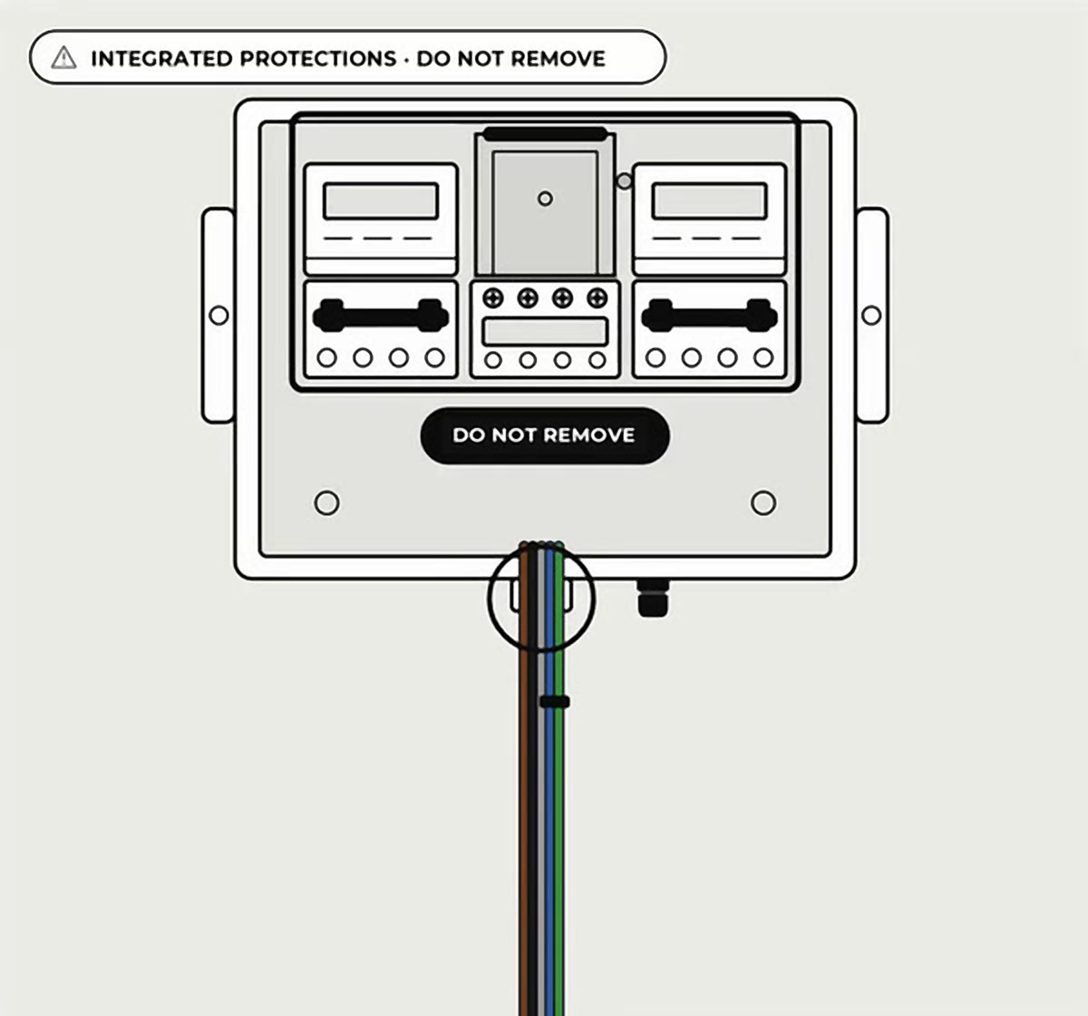

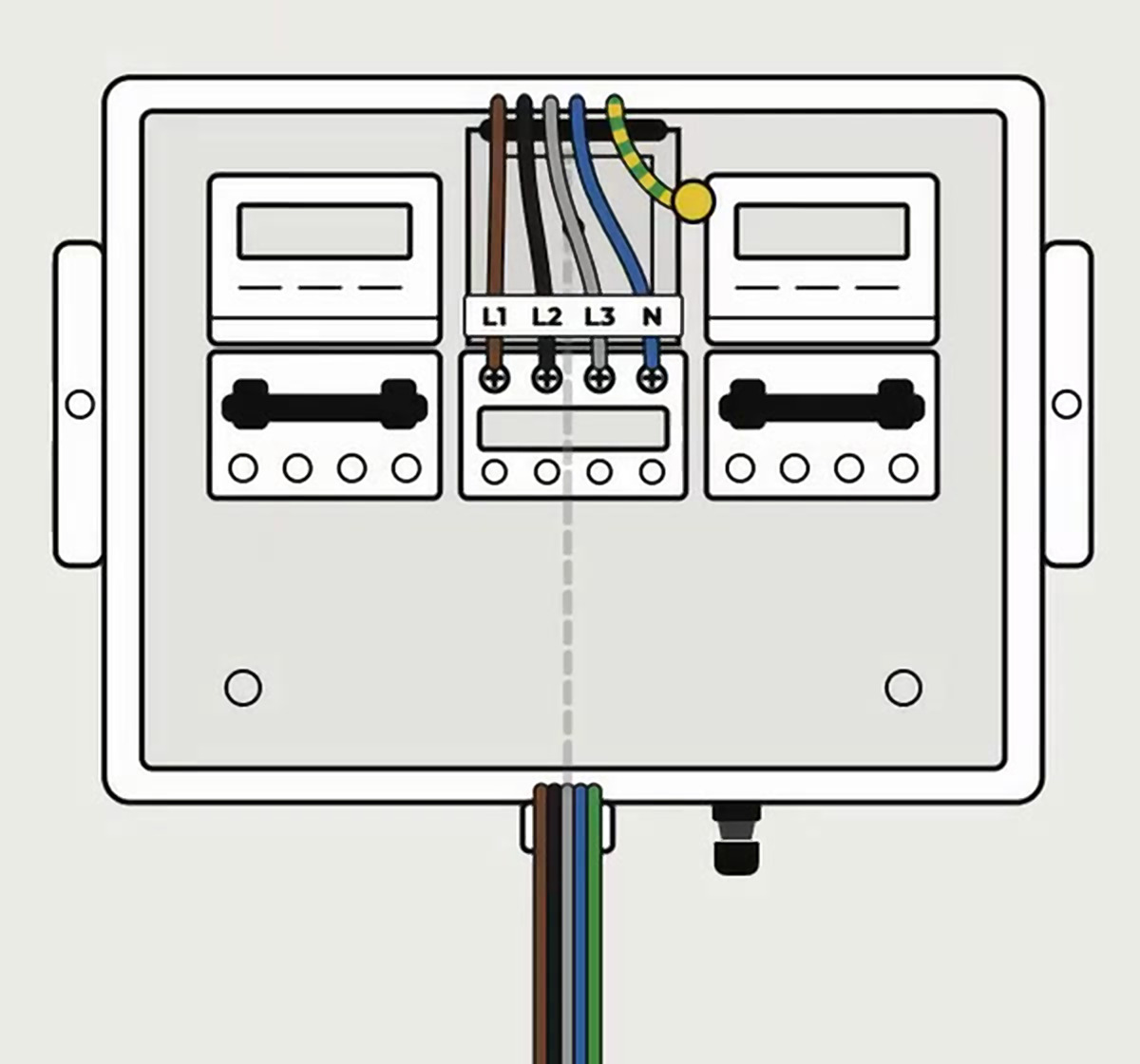
Connect to the main disconnect switch. The cables rise through the entry duct to the top of the charger and connect from above to the main disconnect switch.
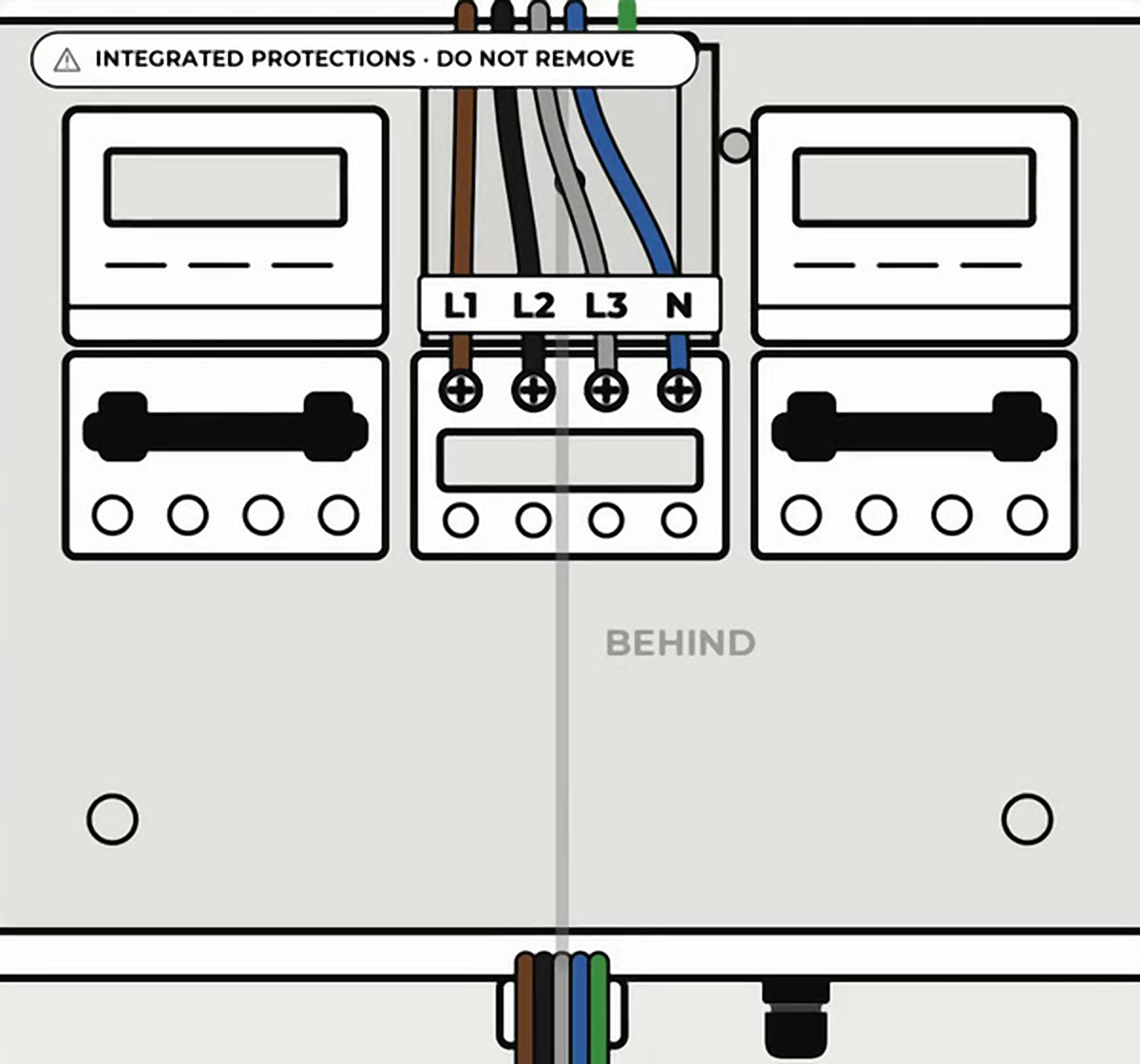
Connection to the input switch
Single-phase: Blue → N · Brown → L1
Three-phase: Blue → N · Brown → L1 · Black → L2 · Gray → L3
Square terminals are required. The ground (green and yellow) is connected in step 7.
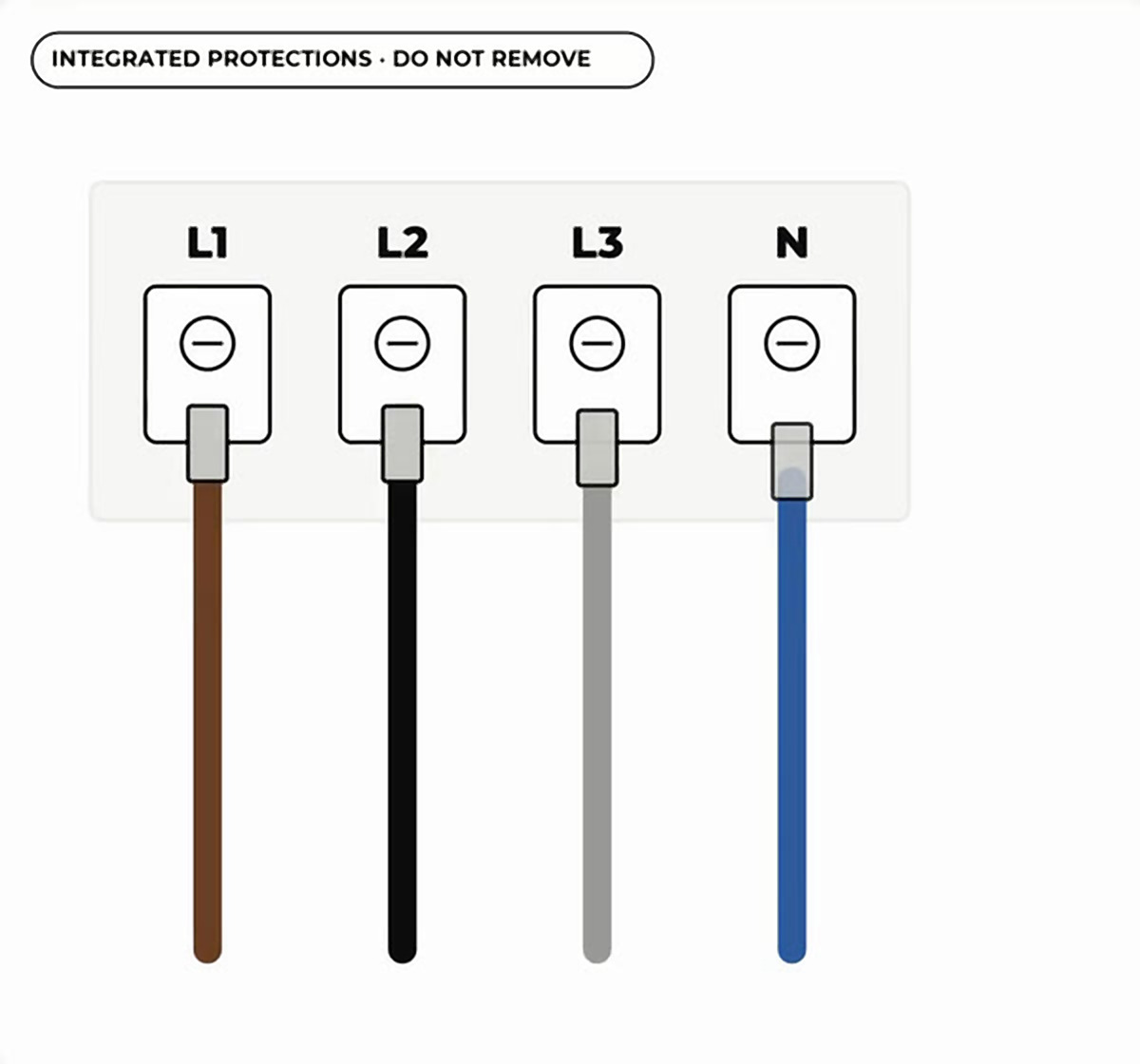

Connect the ground terminal. The green and yellow wire, with its terminal, to the chassis ground terminal.

Pass the data cables. Ethernet and Modbus through the M16 cable gland. Do not tighten the cable gland yet.

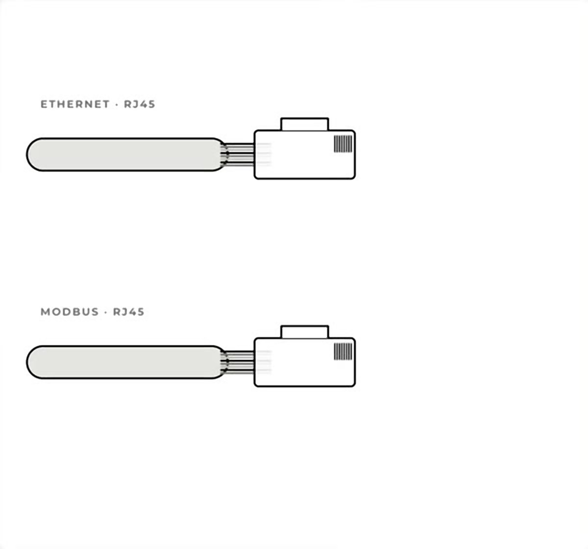
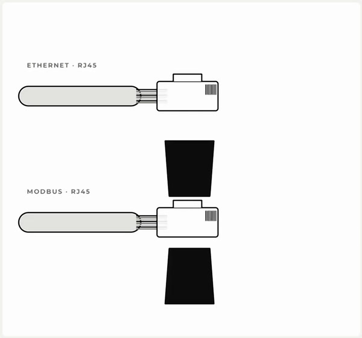
Crimp the connectors. One RJ45 connector on the Ethernet cable and another identical one on the Modbus cable.

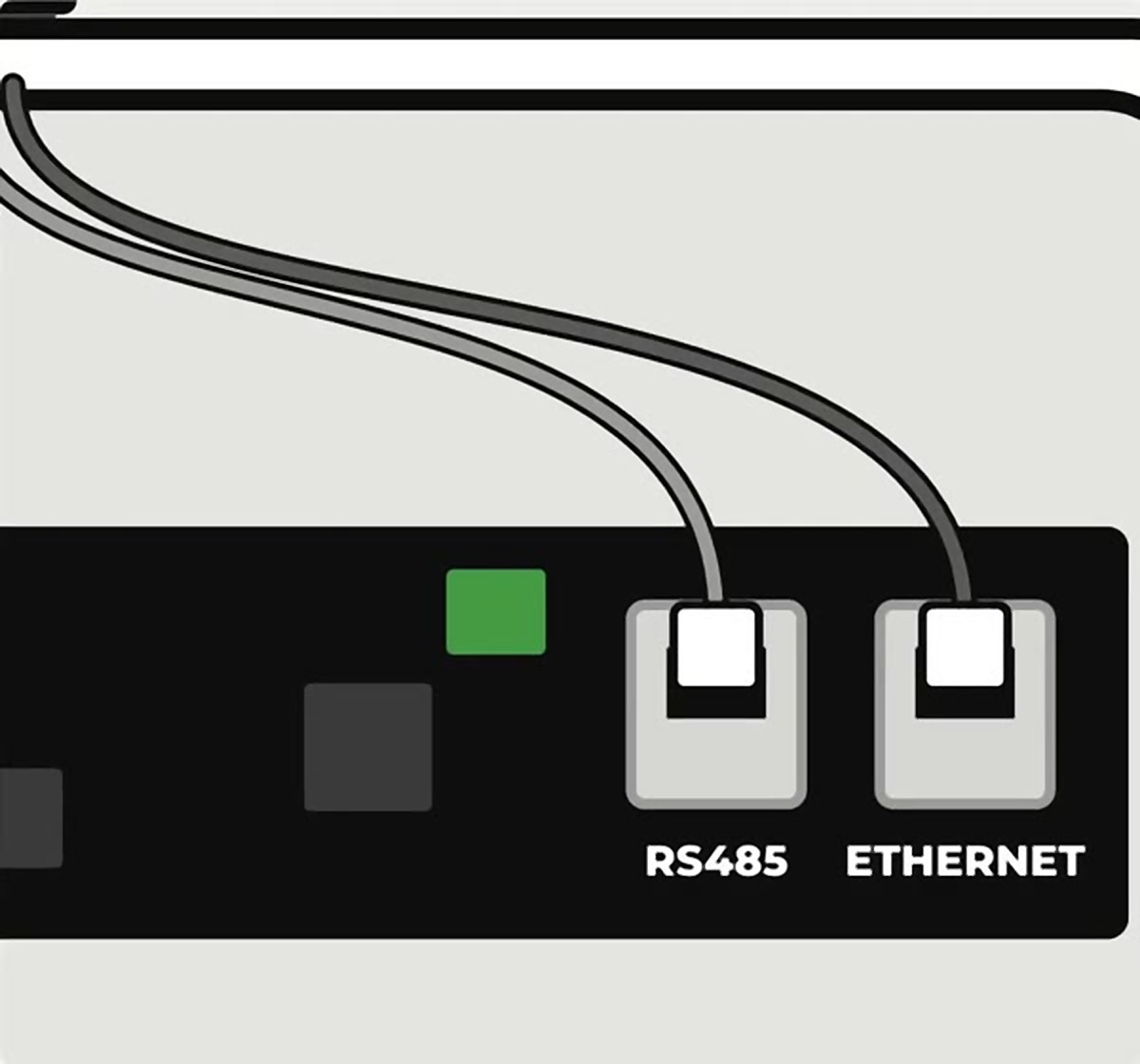
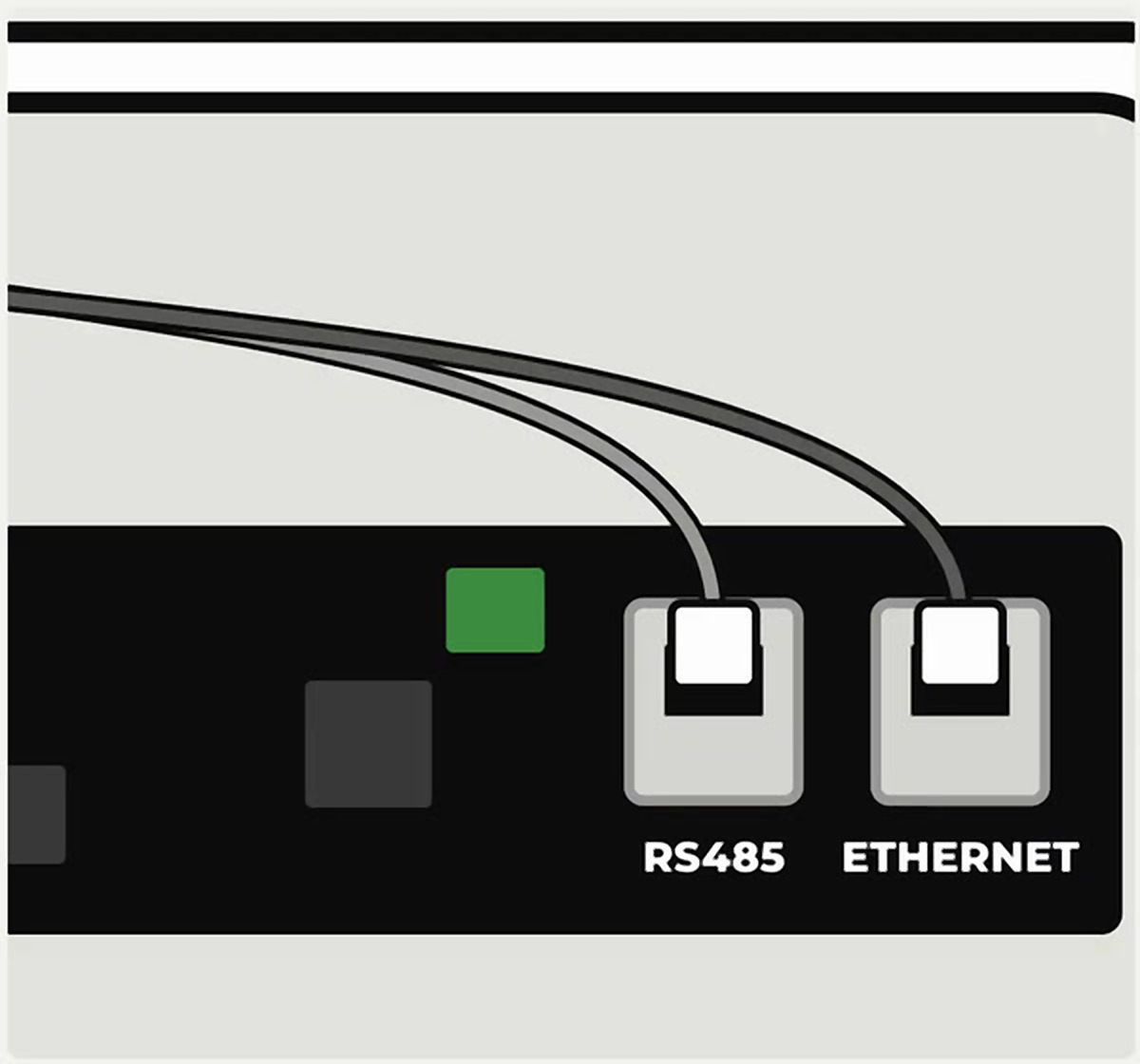
Connect to the door plate. Modbus on the RS485 port and Ethernet on the Ethernet port. Then, tighten the cable gland.

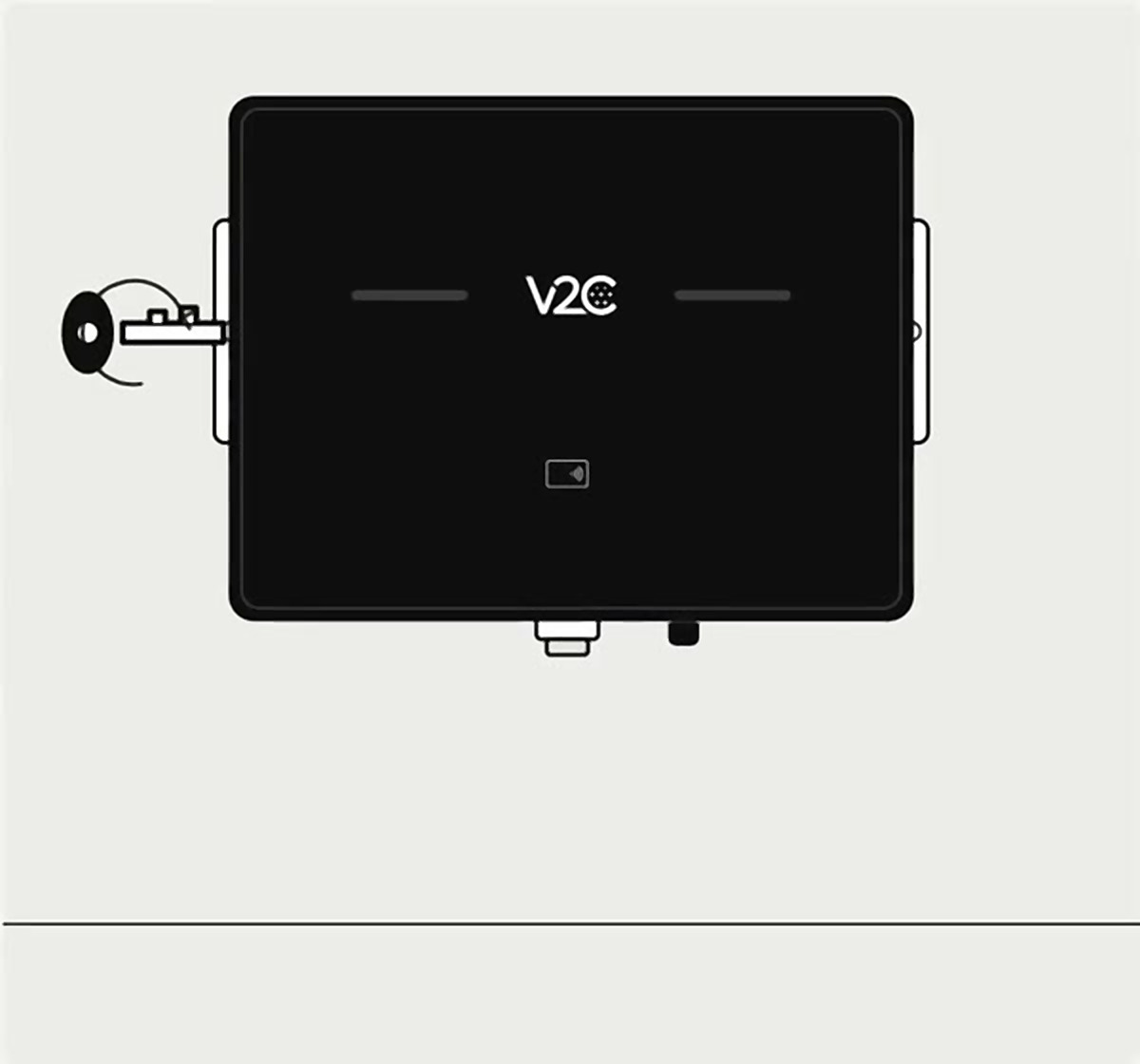
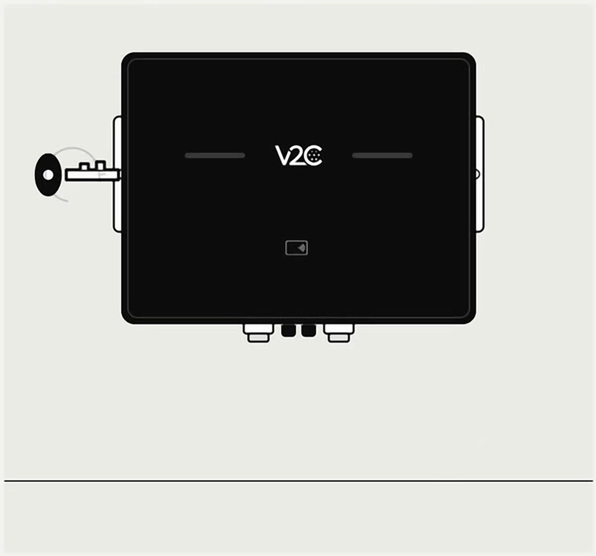
Close the equipment. Close the door and turn the key in both side locks.
Installation of the version without electrical protections
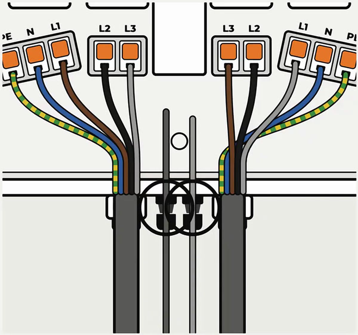
Very important: on the right side, in three-phase installation, connect the brown wire to L3 and the gray to L1. This balances the load between phases. This only applies to the right side.
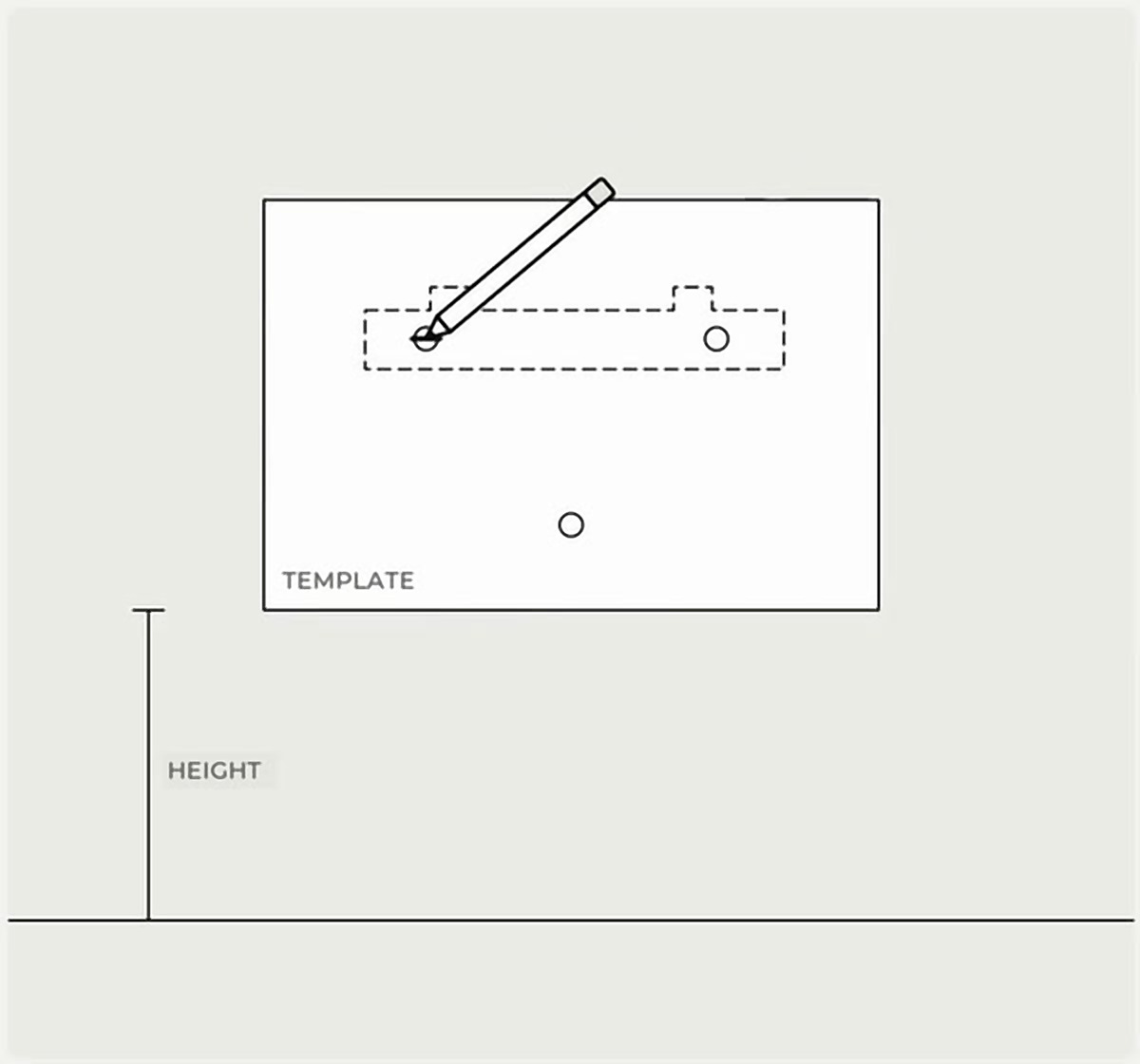
Mark the drill holes. Place the template at the desired height, level it, and mark the three drill holes.
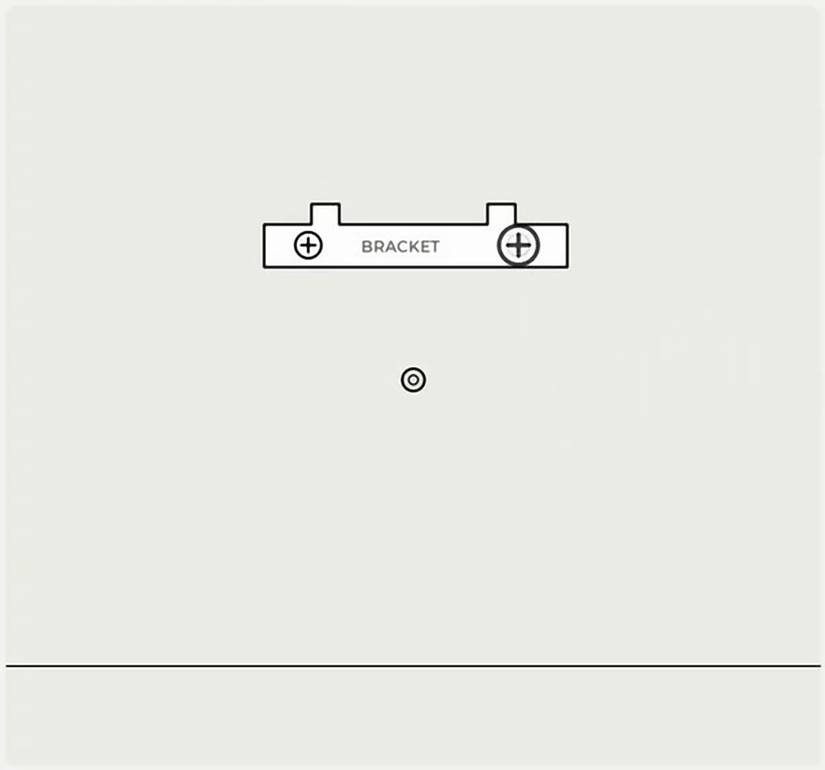
Fix the bracket. Drill the three marks, insert the plugs, and screw the bracket into the two upper holes.
Hang the equipment. Bring the equipment close to the wall and fit it into the bracket.
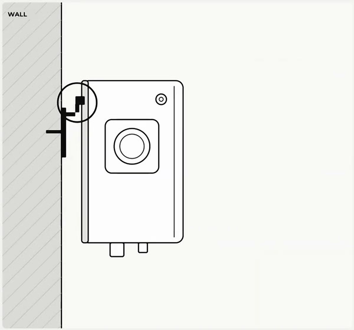
Fix the bottom part. Open the door and, with the box screw, secure the bottom part in the central drill.
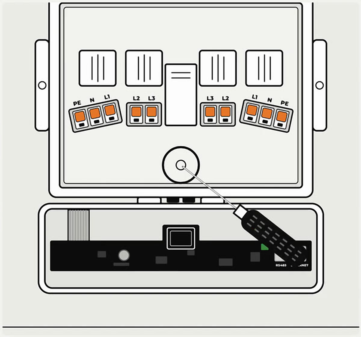
Connect the wires to the terminals. Through the lower entries and then to the electrical terminals.
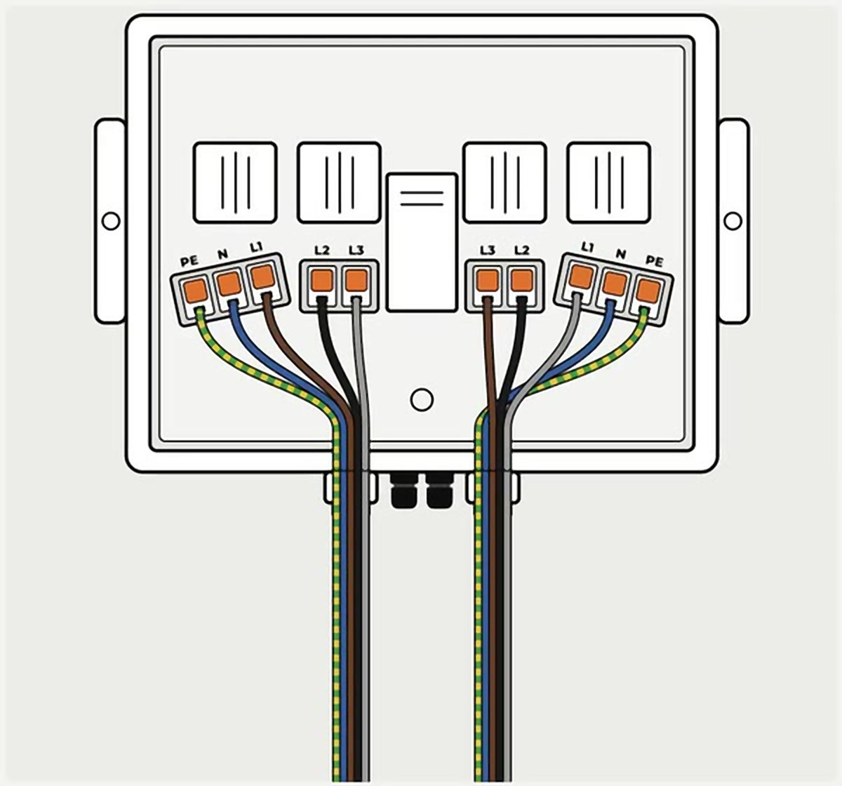
Connection to the terminals
Single-phase: Green/yellow → PE · Blue → N · Brown → L1
Three-phase: Green/yellow → PE · Blue → N · Brown → L1 · Black → L2 · Gray → L3
Right side · three-phase: the brown cable goes to L3 and the gray to L1, to balance the load between the phases. The other cables are connected in the same way on both sides.
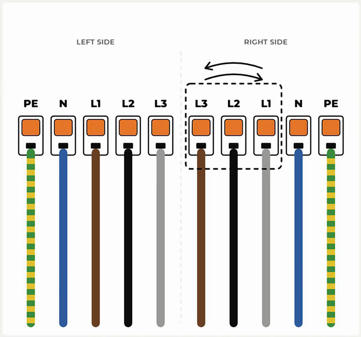
Run the data cables. Ethernet and Modbus, one for each M16 cable gland, still without connectors. Do not tighten the cable glands yet.
Crimp the connectors. One RJ45 connector on the Ethernet cable and another identical one on the Modbus cable.
Connect to the door plate. Modbus on the RS485 port and Ethernet on the Ethernet port. Then, tighten the cable glands.
Close the equipment. Close the door and turn the key in the two side locks.
Electrical installation
To proceed with the electrical installation of the Alva charger, you must connect the power supply line to an existing installation and it must comply with local regulations. Remember that you must adhere to the installation regulations in force both nationally and internationally (for example, IEC 60364-1 and IEC 603645-52).
Selection of the differential switch
You must connect each charging station to its own residual current circuit breaker, which must have a residual operating current that does not exceed 30 mA type A. The protection devices of the installation ensure protection against short circuits; these devices must ensure that <80000 A2s are not exceeded in the event of a short circuit. Remember that other current circuits should not be connected to this residual current circuit breaker. On the other hand, for the chosen circuit breaker, you must select an appropriate rated current IN. (Applicable to the following standards: IEC 60898-1 or IEC 60947-2, IEC 61009-1, IEC 61008, IEC 62423).
Sizing of the circuit breaker
As determined by the nameplate, according to the chosen charging power and the power line, it determines the rated current. According to state regulations, the addition of other protective elements may be necessary. You should consider and take into account the increase in ambient temperatures in the distribution cabinet.
Sizing of the power line
To correctly size the installation, you must follow the guidelines of the current national regulations. Considering the charging properties, take into account the temperature variations that the cable may experience.
Network connection device
The electric charging station does not have a power switch, so the circuit breaker and the differential switch of the power supply line act as a network connection device. The charging point can remain on at all times, and should only be turned off in case of infrequent use.
Sizing of surge protection devices
If national legislation requires the installation of an electric discharge device, it must be sized according to the maximum current of the charging station. It can be incorporated at the charging point by selecting the corresponding accessory.
Electrical Connection
It is recommended that the installed conduit be placed 15 cm inside the charger to prevent water from entering the installed conduit. The power supply connects to the input disconnect located in the charger. These terminals power the entire charging device. It is mandatory to use square terminals.
Electrical Installation Setup
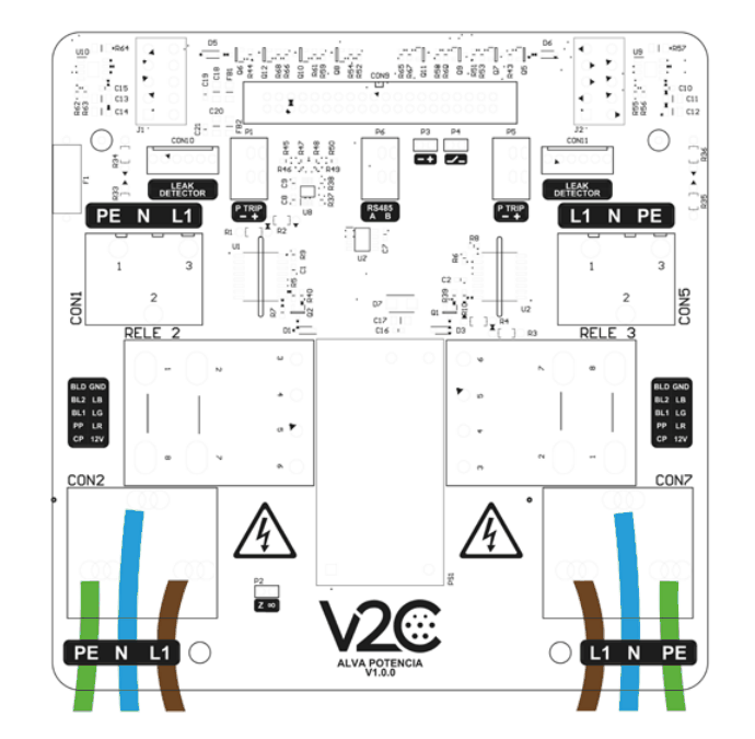
Single-phase configuration. Connect the wires to the terminal block as shown in the drawing: green/yellow wire to ground (PE), blue wire to neutral (N), and brown wire to phase R (L1).
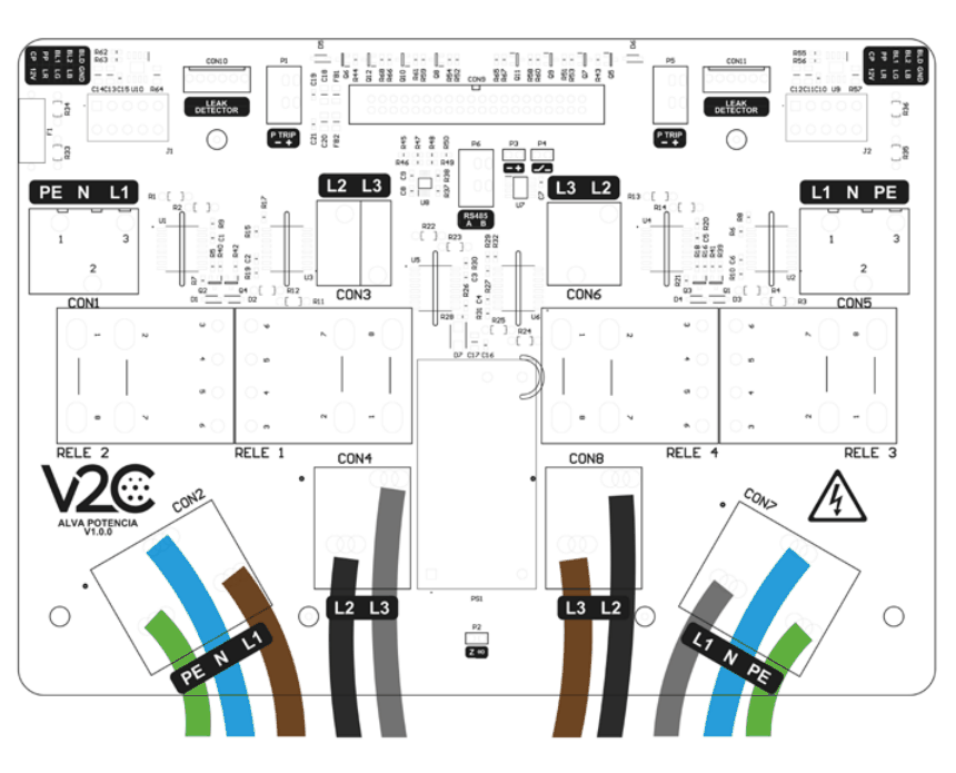
Three-phase configuration. Connect the wires to the connection terminal according to the diagram: green/yellow wire to ground (PE), blue wire to neutral (N), brown wire to phase R (L1), black wire to phase S (L2), and gray wire to phase T (L3).
Installation of dynamic power control (optional)
The dynamic power control allows the Alva charger to automatically adjust the charging power based on the total electrical consumption of the installation, thus preventing exceeding the contracted power and tripping the main circuit breaker (ICP).
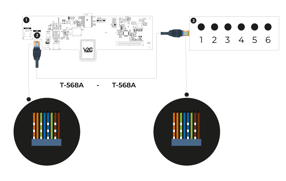
To do this, connect the 8-wire UTP cable between the provided V2C ControlBox balancer and the charger according to the T-568A or T-568B protocol. Both the V2C ControlBox and the charger have an RJ45 input. This is a parallel cable connection: one end connects to the V2C ControlBox balancer and the other end to the charger.
Control panel
RS485/Modbus Connector
V2C ControlBox
For proper operation, it is necessary to install a current clamp (CT) that measures the total consumption of the installation. Learn more about the integration of the V2C ControlBox device.
Configuration in the V2C Cloud app
Once the physical installation of the charger is complete, it is necessary to finish the setup from V2C Cloud, the free V2C app available in both mobile version (iOS and Android) and web version.
Discover in the following video how to create an account, add an e-Charger, pair via Bluetooth, establish the Internet connection, activate and configure power control, and create charging profiles.
We recommend watching the video, as it is the clearest way to understand the mandatory steps for everything to work correctly.
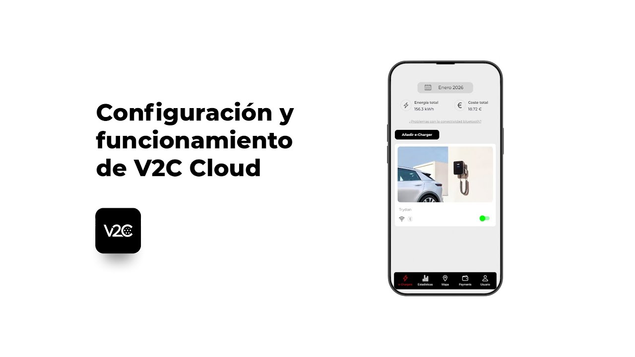
To download the app, create your account, add the e-Charger, and complete the rest of the setup, check our complete V2C Cloud guide. If you have already added the e-Charger, below we explain how to pair the charger via Bluetooth and the different available Internet connection methods, necessary steps to complete the installation.
Three connection methods: WiFi, Ethernet, or 4G
The e-Charger must be connected to the Internet to make all the settings from the app. But before that, you need to make the first connection by positioning yourself next to the charger and linking it via Bluetooth:
1. Turn on Bluetooth on your mobile.
2. Swipe down to refresh the main screen of the app.
3. You will see the Bluetooth icon activated, confirming that the connection has been established.
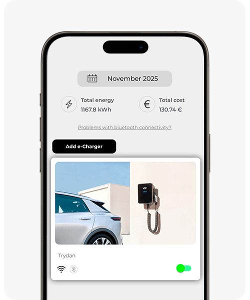
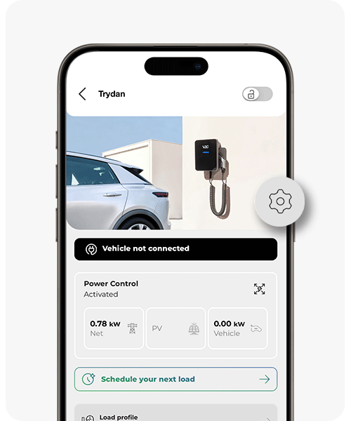
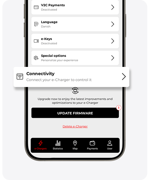
Now, to connect the e-Charger to the Internet, follow the steps in the images:
1. Select one of the charger sockets.
2. Access the Settings menu.
3. Choose Connectivity and select the type of connection you want to use. Keep reading to learn more about the three connection options.
By default, Alva will be automatically connected to the network via 4G.
WiFi Connection
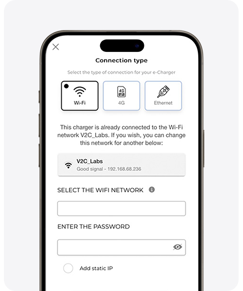
To establish the connection via WiFi, you must select the desired WiFi network name (the SSID) and the corresponding password.
If the network you want to use does not appear in the list, enter the wireless network details exactly as they appear on the router (respecting uppercase and lowercase letters) and provide the password.
Once the connection is established, the e-Charger will proceed to restart. After a few minutes from the restart, check that the e-Charger has the active WiFi icon. If not, verify that the password is correct or check that your mobile device has an internet connection.
Additionally, you can select the option to create a static IP and configure it according to the user’s needs.
If the connection via WiFi has been successfully established, you will see on the screen the name of the WiFi network, the signal level of that network, and the IP address of the e-Charger.
WiFi networks from certain companies have some type of security protection (firewall), DHCP blocking, port closing, etc. In this case, the configuration must be carried out by the technical manager of the network. For more information, please contact our support service.
4G Connection
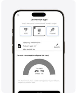
The charger comes standard with a SIM card with 500 MB of data, ready for use. If you prefer, you can also use a SIM card from any other operator on the market. Remember to remove the PIN code from the SIM card before inserting it into the corresponding slot on the control board.
Ethernet Connection
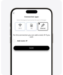
To make this type of connection, connect the network cable to the corresponding port on the control board. The connection is made automatically. DHCP must be set to automatic mode (IP assignment).
You can also select a static IP and the e-Charger will always have the same address when connected to the Internet.
Attention: remember that if you have installed dynamic power control, you must activate and configure it, as well as customize the charging profiles according to the contracted power, so that everything works correctly. For this, consult the complete V2C Cloud guide.
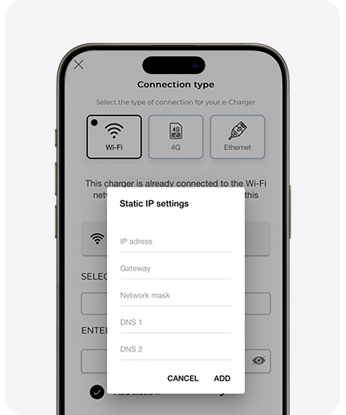
You can select “Add Static IP” for WiFi and Ethernet connection types in order to identify the Alva charger on the network. Using the pencil icon that appears to the right of “Add Static IP,” you can edit the static IP settings. By configuring a static IP address, you ensure that the charger always has the same IP address on your local network. This is a very useful feature for accessing the charger remotely or for configuring services that depend on a fixed IP, such as integration with other applications or smart home systems.
To configure the static IP, you must select the following parameters:
IP Address: Enter a specific IP address that will identify the charger on the local network.
Gateway: Enter the IP address of the router or gateway that connects the local network to the Internet. (All devices on the network use this parameter to communicate with devices outside the local network)
Subnet Mask: Define this parameter to identify which part of the IP address refers to the local network and which part refers to the devices on that network. This will determine which devices are on the same local network and which need to go through the gateway to communicate.
DNS (Domain Name Server): Enter the necessary DNS. These servers translate domain names into IP addresses that devices can understand. You can define DNS1 and DNS2 to be used in case of failure.


General features
e-Charger
Alva

Color
Black

Material
MVR Polycarbonate

Weight
9-20kg depending on the version

Outlet
Cable or socket

Operating temperature
-25ºC to 50ºC
Storage Temperature
-40ºC to 70ºC

Lighting according to the charging status
Safety warnings to keep in mind

Risk of electric shock

Waste Projection
Risk of injury

Ground connection required
Warning! Failure to comply with safety instructions may result in the risk of death, personal injury, and equipment damage. V2C disclaims all liability for rights arising from such non-compliance.
Electrical hazard! The installation, initial commissioning, and maintenance of the charging station must be carried out exclusively by fully qualified technical personnel for the tasks and competent, fully responsible for the excellent compliance with the installation provisions and existing standards.
This e-Charger in mode 3 is classified according to section 5 of UNE·EN 61851·1 in a VE power supply system connected to an AC supply network. Depending on the chosen version, the VE power supply will be either plug and cable or permanently connected. This charging station can be used both outdoors and indoors and can be used with restricted or unrestricted access. The installation is on wall/post/column/ceiling mount, and on a flat surface. It has Class II electric shock protection.

V2C carries the CE mark. V2C applies the corresponding declarations of conformity.

V2C complies with the ROHS directive (2011/65/EU). V2C applies the corresponding declarations of conformity.

Electrical and electronic equipment, as well as their accessories, must be disposed of separately from household waste.
Do you need technical support?
Resolve your issue instantly through our AI Chat. If it is not resolved, generate a request in the Technical Support Center and we will contact you as soon as possible to offer you the best solution.