
Installation Manual for Trydan
The installation of an e-Charger is a crucial step for its correct operation. Therefore, it is essential to understand the risks, necessary steps and tools required to carry out a safe and successful installation.
In this manual, we have compiled detailed information to guide you through the installation process of our Trydan e-Charger. Here you will find everything you need to know to carry out this task with precision.
This manual is subject to change without notice. The images contained in this manual are representative and may differ slightly from the actual products.

You can also download the complete installation manual in PDF.
Tools required for installation

Drill

Hammer

Crown drill bit

Screwdriver

Measuring tape

Leveller and pencil
Accessories included in the recharging point

1x
Cable glands

4x
N+Plus Nylon Plug 6x30mm.

4x
Zinc-plated star screw with 04,8x32mm.

4x
Plug BLG Barrel BK
15,9×8,5mm.

5x
Pan head screw with 3x6mm washer.

1x
Methacrylate protector with Ø6mm holes.

TRYDAN ONLINE COURSE
Do you want to know in detail the configuration and commissioning of the charger?
Do you install the charger on a pedestal?
Check the pedestal installation instructions here.
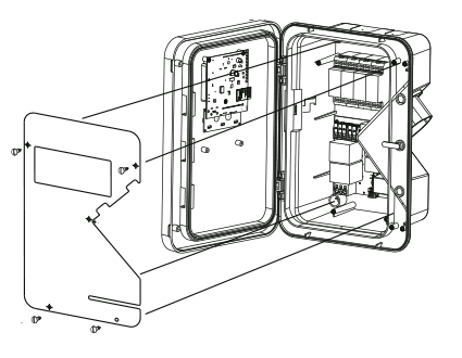
Follow these steps for the installation of the e-Charger

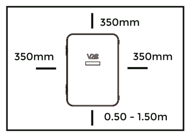
Ensure safe distances for installation.

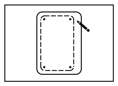
Place the template over the installation space and mark the drilling points with a pencil.

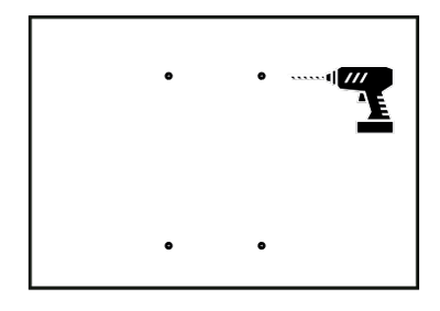
Drill over the drilling points with a ø6mm drill bit.

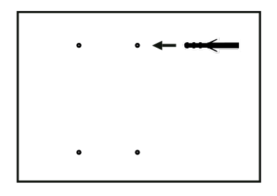
Insert the ø6x30mm Taco N+Plus Nylon plugs.

Drill a hole on the top of the charger’s case with the crown bit*. Place the cable gland and pass the cable through it.
*In outdoor installations or those with potential humidity/water ingress, the conduit must be routed from below the charger to avoid direct exposure to rain. In this case, drilling should be done initially with a drill bit (never with a hole saw) and at a maximum distance of 5mm from the charger to prevent damage to the power board and its flat cable. The hole must be sealed, and all four plugs must be installed without exception.


Place the e-Charger on the wall and match the holes with the previously drilled holes.


Insert the ø4,8x32mm zinc-plated pan-head screws and then the plugs.


Connect the wires to the protections (if present) or to the electrical terminals (if not present).


Screw on the acrylic plexiglass protector with ø3×6,8mm.
Wiring installation
The power supply line must be connected to an existing installation and must conform to local regulations. Observe the applicable national and international installation standards (e.g. IEC 60364-1 and IEC603645-52).
Selection of the residual current circuit breaker (RCD)
Each charging station must be connected to its own residual current circuit breaker. No other current circuits must be connected to this residual current circuit breaker. A suitable rated current IN must be selected for the circuit breaker fitted. (In accordance with each country’s standard).
Circuit breaker sizing (MCB)
Determine the rated current according to the data on the rating plate, in accordance with the selected load power and the supply line. Depending on the national regulations, it may be necessary to add additional protection elements.
Sizing of the supply line
When sizing the installation, ensure compliance with the prevailing state-level regulations. Consider the cable’s temperature tolerance based on the load characteristics.
Network connection device
The charging station does not have a power switch. The differential and the circuit breaker in the supply line act as a mains connection device. The charging station can be switched on at all times and only switched off in the event of infrequent use.
Electrical installation configuration
Single-phase configuration with protections. Connect the cables to the terminal block according to the diagram: green/yellow cable (1) to the PE terminal, blue cable (2) to the N terminal, and brown cable (3) to the L1 terminal.
Trydan power board
Protections for single-phase installation

Single-phase configuration. Connect the cables to the terminal block according to the diagram: green/yellow cable (1) to ground or equipotential bonding (PE), blue cable (2) to neutral (N), and brown cable (3) to phase R (L1).
Trydan power board

Three-phase configuration. Connect the cables to the terminal block according to the diagram: green/yellow cable (1) to ground or equipotential bonding (PE), blue cable (2) to neutral (N), brown cable (3) to phase R (L1), black cable (4) to phase S (L2), and grey cable (5) to phase T (L3).
Trydan power board

Fitting and removal of the hose
Hose setup
- Insert the hose into the hose holder leaving a small gap at the bottom, so that it does not collide with the integrated locking clip.
- Slide the hose down to engage it into the integrated locking clip.

Hose removal
- Slide the hose upwards to release it from the locking clip.
- Pull the hose outwards, out of the holder.


General characteristics

e-Charger
Trydan

Colour
⚫ Black

Material
PolycarbonateMVR

Hose length
5m / 10m

Weight
7 kg

Hose type
Smooth / Spring

Operating temperature
-25ºC to 50º
Storage temperature
-40ºC to 70º

Display
Yes

Lighting depending on state of charge
Safety warnings

Risk of electric shock

Projection of debris
Risk of injury

Grounding required
WARNING! Failure to comply with the safety instructions may result in danger to life, personal injury and damage to the device. V2C accepts no liability for any claims resulting from such non-compliance.
Electrical hazard! The installation, initial start and maintenance of the electrical charging station may only be carried out by qualified and competent personnel who are fully responsible for compliance with the existing installation regulations and standards.
This mode 3 charging point is classified according to section 5 of UNE-EN 61851-1 in an EV power supply system connected to an AC supply network. Depending on the version chosen, the EV power supply system will be plug and cable or permanently connected. It can be used both outdoors and indoors and can be used in both restricted and unrestricted access. Mounting is on a wall/post/column, and on a flat surface. It has a class II electric shock protection.
V2C bears the CE symbol. V2C applies the corresponding declarations of conformity.
V2C complies with the ROHS directive (2077/65/EC). V2C applies the corresponding declarations of conformity.

Electrical and electronic equipment and its accessories should be disposed of separately from household waste.
Do you need technical support?
Resolve your issue instantly through our AI Chat. If it is not resolved, submit a request via the Technical Support Centre and we will contact you as soon as possible to provide the best solution.