
Pole Pro Control Board Replacement: V1, V2 and V3
If you need to replace the control board of a Pole Pro charger and the new board you have received is a different version from the one installed, you will need to re-route the wiring according to the correspondence between the connectors of both versions.
This guide explains how to identify each version, the general procedure, and the pin-to-pin equivalence for all three possible cases: from V1 to V2, from V1 to V3, and from V2 to V3.
Model
Pole Pro · wall version
Operation
Control board replacement
For
Authorised installer
⚠️ Safety
Work inside the charger must only be carried out by an authorised installer, with the unit powered off and after verifying the absence of voltage.
Do not power the unit until you have checked all connections, especially +12V and GND.
Identify the version of each board
Before you start, check which version the installed board is and which is the new one. You can recognise them by the colour, the silkscreen, and the connectors for the charging outlets:
| POLE V1 | POLE V2 | POLE V3 | |
|---|---|---|---|
| Board | Green | White · silkscreen POLE V2.1 | White PLC · silkscreen POLE V3.0.0 |
| Left charging outlet | CN10 + CN6 (9-pole terminal blocks) | J1 (16 pins) | CN9 (16 pins) |
| Right charging outlet | CN8 + CN5 (9-pole terminal blocks) | J2 (16 pins) | CN6 (16 pins) |
| PP (proximity) | CN6·2 / CN5·2 | Pin 2 | Pin 8 |
| Contactors | CN19 (left) · CN18 (right) | CN14 (left) · CN16 (right) | CN10 · RELÉ 01 (left) · CN7 · RELÉ 02 (right) |
| Leakage sensor | On the outlet terminal blocks (FUGA_1 / FUGA_2) | CN15 (left) · CN17 (right) | CN11 (left) · CN8 (right) |
| Power supply | GND/TIERRA · +12V | CN1 · GND · +12V | CN1 · GND · +12V · PE |
| RS485 | CN10·8 and CN10·9 | J1·6 / J1·14 and green terminal block A · B | CN9·6 / CN9·14 and CN16 · A+ · B- |
General procedure
These steps are the same in all three cases. The only thing that changes is where each cable goes (step 6).
01
Isolate the unit from power
Switch off the circuit breaker and the RCD supplying the Pole Pro. Use a tester to confirm there is no voltage before opening the unit.
02
Photograph the old board
Before disconnecting any cables, take clear photos of the old board with all connectors visible, like these. They will serve as a reference and can be sent to technical support if you have any questions.
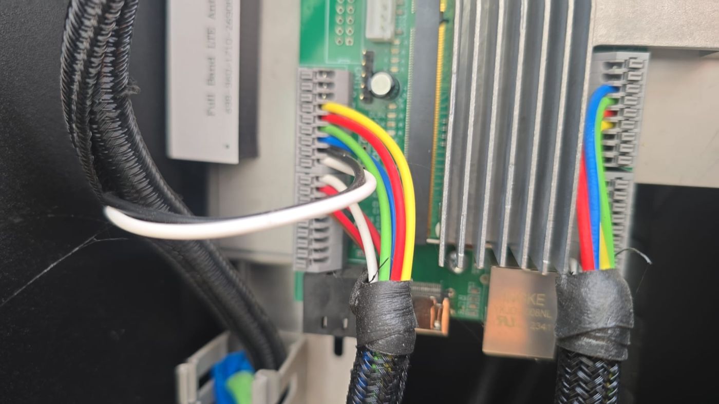
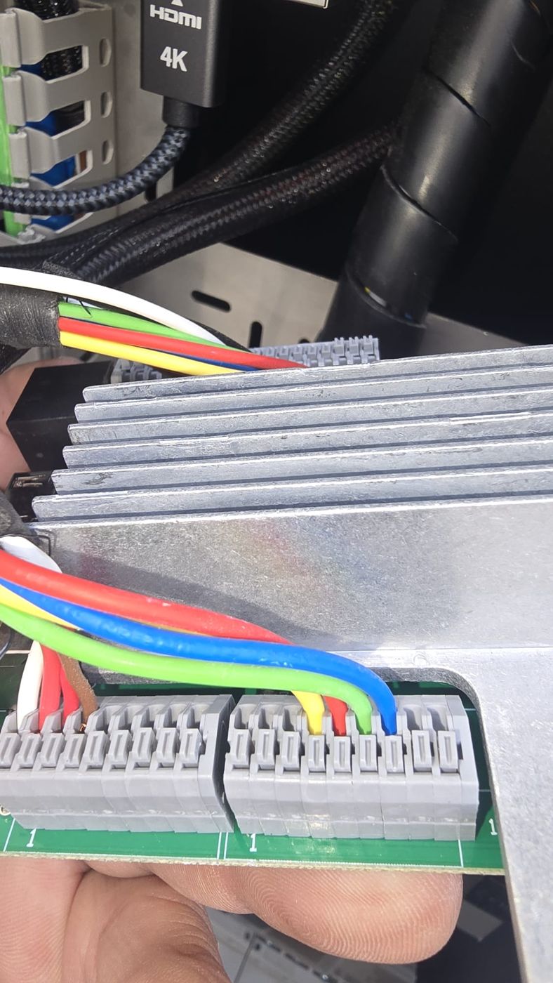
03
Label each cable
Each outlet comes with its own coloured cable harness. Colours may vary between units, so do not rely on colour alone: label each cable with its signal name (for example, CP_IZQ, PP_DER or LED_V_CON_DER), not with the terminal number. Terminal numbers change between boards; signal names do not.
04
Disconnect and remove the old board
Disconnect the cables from the outlets, contactors, leakage sensor, and power supply. The table “Identify the version of each board” shows which connectors are used by each version. Remove the board by holding it by the edges.
05
Install the new board
Secure the new board in the same position. Handle it with anti-static precautions and avoid touching the components.
06
Connect the cables according to your case
Follow the guide for your case (V1 to V2, V1 to V3, or V2 to V3). On 16-pin connectors, the numbering goes by columns: pins 1 to 8 in one column and 9 to 16 in the other. On V2 and V3, facing the board, pins 9 to 16 are in the left column and 1 to 8 in the right. Always check the board silkscreen.
07
Check before powering up
Check that each cable is properly secured, that there are no loose wires or exposed copper, and that no cable is left in a terminal marked as not connected. Pay special attention to +12V, GND and, if upgrading to V3, that PP is on pin 8.
08
Power up and test
Close the unit, restore power, and check both outlets: LED indicators, connector locking, RS485 communication, and a full charging session with a vehicle.
Choose your case
Open the dropdown that matches your replacement. If you are unsure which version you have, see the table “Identify the version of each board”.
Case 1 · From POLE V1 to POLE V2
The green board (V1) splits each outlet into two 9-pole terminal blocks. The white board (V2) groups them into a single 16-pin connector: J1 (left outlet) and J2 (right outlet).
⚠️ Important: when replacing the board, you will also need to add the leakage sensor installation. On the V2 board it connects to CN15 (left outlet) and CN17 (right outlet).
Visual guide: where each colour cable goes
The colours shown are from the Pole Pro in the photos; if your unit uses different colours, follow the signal name.
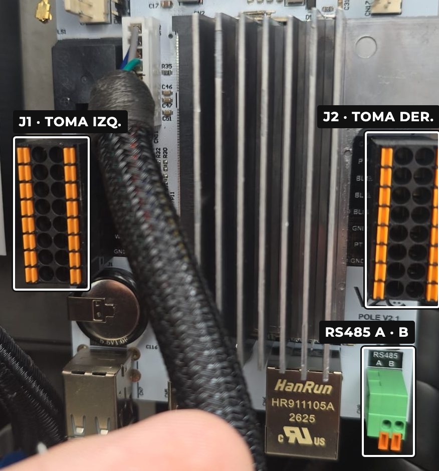
V2 board (silkscreen POLE V2.1) installed: J1 to the left of the heatsink, J2 to the right, and green RS485 A/B terminal block below J2.
Left outlet · CN10 + CN6 → J1
On the V1 board, the two terminal blocks are stacked vertically and form a single continuous column: CN10 on top (pins 1 to 9) and CN6 below (pins 1 to 9).
Old board photo
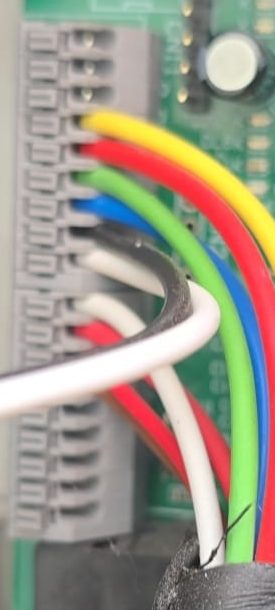
Old board · top to bottom
- 1GND
- 2FUGA_1
- 3FUGA_2
- 4+12V (yellow wire)
- 5LED_R (red wire)
- 6LED_V (green wire)
- 7LED_A (blue wire)
- 8RS485_A (black wire)
- 9RS485_B (white wire)
- 1CP (white wire)
- 2PP (red wire)
- 3BLOQUEO_1 (red wire)
- 4BLOQUEO_2 (brown wire)
- 5GND
- 6+5V
- 7not used
- 8GND
- 9+12V
V2 Board
| 9 · +12VYellow | 1 · CPWhite | ||
| 10 · LED_RRed | 2 · PPRed | ||
| 11 · LED_VGreen | 3 · BL1Red | ||
| 12 · LED_ABlue | 4 · BL2Brown | ||
| 13 · GND | 13 | 5 | 5 · BLD |
| 14 · RS485_BWhite | 6 · RS485_ABlack | ||
| 15 · DET_SOLD | 15 | 7 | 7 · PT |
| 16 · GND | 16 | 8 | 8 · GND |
Right charging socket · CN8 + CN5 → J2
On the right socket, the column is reversed: CN8 on top (from pin 9 to 1) and CN5 below (from pin 9 to 1).
Photo of old board
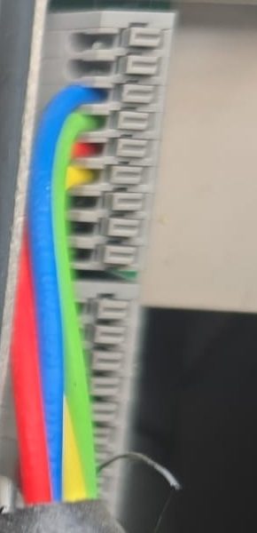
Old board · top to bottom
- 9not used
- 8not used
- 7LED_A (blue wire)
- 6LED_V (green wire)
- 5LED_R (red wire)
- 4+12V (yellow wire)
- 3FUGA_2
- 2FUGA_1
- 1GND
- 9+12V
- 8GND
- 7not used
- 6+5V
- 5GND
- 4BLOQUEO_2 (brown wire)
- 3BLOQUEO_1 (red wire)
- 2PP (red wire)
- 1CP (white wire)
V2 Board
| 9 · +12VYellow | 1 · CPWhite | ||
| 10 · LED_RRed | 2 · PPRed | ||
| 11 · LED_VGreen | 3 · BL1Red | ||
| 12 · LED_ABlue | 4 · BL2Brown | ||
| 13 · GND | 13 | 5 | 5 · BLD |
| 14 · FALLO_ENER | 14 | 6 | 6 · GND |
| 15 · DET_SOLD | 15 | 7 | 7 · PT |
| 16 · GND | 16 | 8 | 8 · GND |
Be careful with the red wires. Each harness contains three red wires: PP and BLOQUEO_1 (coming from the CN6/CN5 block, together with the white and brown wires) and LED_R (coming from the CN10/CN8 block, together with the yellow, green, and blue wires). Label them before disconnecting. On the left charging socket there are also two white wires: CP (in the harness) and RS485_B (in the communication cable, together with the black wire).
Signal-to-signal equivalence
How to read the status. Direct the signal goes to the same place or has a direct equivalent. Pin changed the signal exists on both boards, but is on a different pin. Check the connection type changes or there is no direct equivalent: confirm with technical support before powering up. Not connected the terminal is left unused.
| Signal | POLE V1 | POLE V2 | Status |
|---|---|---|---|
| Earth / GND + 12V | GND/TIERRA connector | CN1 | Direct |
| CON_IZQ_1 / CON_IZQ_2 | CN19 · 1 and 2 | CN14 · 1 and 2 | Direct |
| CON_DER_1 / CON_DER_2 | CN18 · 1 and 2 | CN16 · 1 and 2 | Direct |
| Signal | POLE V1 | POLE V2 | Status |
|---|---|---|---|
| CP_IZQ | CN6 · 1 | J1 · 1 | Direct |
| PP_IZQ | CN6 · 2 | J1 · 2 | Direct |
| BLOQUEO_IZQ_1 | CN6 · 3 | J1 · 3 | Direct |
| BLOQUEO_IZQ_2 | CN6 · 4 | J1 · 4 | Direct |
| GND | CN6 · 5 and 8 · CN10 · 1 | J1 · 8, 13 or 16 | Direct |
| +5V | CN6 · 6 | Not present on V2 board | Check |
| +12V | CN6 · 9 · CN10 · 4 | J1 · 9 | Direct |
| LED_R / LED_V / LED_A | CN10 · 5, 6 and 7 | J1 · 10, 11 and 12 | Direct |
| RS485_A | CN10 · 8 | J1 · 6 (or green RS485 A terminal block) | Check |
| RS485_B | CN10 · 9 | J1 · 14 (or green RS485 B terminal block) | Check |
| FUGA_IZQ_1 / FUGA_IZQ_2 | CN10 · 2 and 3 | CN15 · 3 and 4 | Check |
| Signal | POLE V1 | POLE V2 | Status |
|---|---|---|---|
| CP_DER | CN5 · 1 | J2 · 1 | Direct |
| PP_DER | CN5 · 2 | J2 · 2 | Direct |
| BLOQUEO_DER_1 | CN5 · 3 | J2 · 3 | Direct |
| BLOQUEO_DER_2 | CN5 · 4 | J2 · 4 | Direct |
| GND | CN5 · 5 and 8 · CN8 · 1 | J2 · 6, 8, 13 or 16 | Direct |
| +5V | CN5 · 6 | Not present on V2 board | Check |
| +12V | CN5 · 9 · CN8 · 4 | J2 · 9 | Direct |
| LED_R / LED_V / LED_A | CN8 · 5, 6 and 7 | J2 · 10, 11 and 12 | Direct |
| FUGA_DER_1 / FUGA_DER_2 | CN8 · 2 and 3 | CN17 · 3 and 4 | Check |
| Unused terminals | CN6 · 7 · CN5 · 7 · CN8 · 8 and 9 | — | No connection |
| Signal | CN15 (left) | CN17 (right) | Status |
|---|---|---|---|
| +12V | Pin 1 | Pin 1 | Direct |
| GND | Pin 2 | Pin 2 | Direct |
| FUGA_1 | Pin 3 | Pin 3 | Direct |
| FUGA_2 | Pin 4 | Pin 4 | Direct |
| Not used | Pins 5 and 6 | Pins 5 and 6 | No connection |
RS485. According to the diagram, RS485_A and RS485_B go to J1·6 and J1·14. The V2 board also has a dedicated green terminal block RS485 A · B. Before connecting the communication cable, check with technical support which one you should use. The V2 board does not have a +5V output: leave the wires from CN6·6 and CN5·6 isolated.
Case 2 · From POLE V1 to POLE V3
The green board (V1) splits each charging socket into two 9-pole terminal blocks. The V3 board (white PLC) combines them into a single 16-pin connector: CN9 (left socket) and CN6 (right socket).
⚠️ Important: when replacing the board, you will also need to install the leakage sensor. On the V3 board, it connects to CN11 (left socket) and CN8 (right socket).
Watch the names: some connectors have the same name on both boards but are completely different. On V1, CN6, CN8 and CN10 are terminal blocks for the sockets; on V3, CN6 is the right socket, CN8 is the right leakage sensor, and CN10 is the left contactor (RELÉ 01). Always refer to the board you are working with.
Left charging socket · CN10 + CN6 (V1) → CN9 (V3)
On the V1 board, both terminal blocks form a single column: CN10 on top (pins 1 to 9) and CN6 below (pins 1 to 9). On the V3, PP goes to pin 8.
Old board photo
V1 board · top to bottom
- 1GND
- 2FUGA_1
- 3FUGA_2
- 4+12V (yellow wire)
- 5LED_R (red wire)
- 6LED_V (green wire)
- 7LED_A (blue wire)
- 8RS485_A (black wire)
- 9RS485_B (white wire)
- 1CP (white wire)
- 2PP (red wire)
- 3BLOQUEO_1 (red wire)
- 4BLOQUEO_2 (brown wire)
- 5GND
- 6+5V
- 7not used
- 8GND
- 9+12V
V3 Board
| 9 · +12VYellow | 1 · CPWhite | ||
| 10 · LED_RRed | 2 | 2 · PENew | |
| 11 · LED_VGreen | 3 · BL1Red | ||
| 12 · LED_ABlue | 4 · BL2Brown | ||
| 13 · GND | 13 | 5 | 5 · BLD |
| 14 · RS485_BWhite | 6 · RS485_ABlack | ||
| 15 · DET_SOLD | 15 | 7 | 7 · PT |
| 16 · GND | 16 | 8 · PPRed |
Right charging socket · CN8 + CN5 (V1) → CN6 (V3)
On the right socket of the V1, the column is reversed: CN8 on top (from pin 9 to 1) and CN5 below (from pin 9 to 1).
Old board photo
V1 Board · top to bottom
- 9not used
- 8not used
- 7LED_A (blue wire)
- 6LED_V (green wire)
- 5LED_R (red wire)
- 4+12V (yellow wire)
- 3FUGA_2
- 2FUGA_1
- 1GND
- 9+12V
- 8GND
- 7not used
- 6+5V
- 5GND
- 4BLOQUEO_2 (brown wire)
- 3BLOQUEO_1 (red wire)
- 2PP (red wire)
- 1CP (white wire)
V3 Board
| 9 · +12VYellow | 1 · CPWhite | ||
| 10 · LED_RRed | 2 | 2 · PENew | |
| 11 · LED_VGreen | 3 · BL1Red | ||
| 12 · LED_ABlue | 4 · BL2Brown | ||
| 13 · GND | 13 | 5 | 5 · BLD |
| 14 · FALLO_ENER | 14 | 6 | 6 · GND |
| 15 · DET_SOLD | 15 | 7 | 7 · PT |
| 16 · GND | 16 | 8 · PPRed |
Be careful with the red wires. Each harness has three red wires: PP (goes to pin 8), BLOQUEO_1 (pin 3), and LED_R (pin 10). Label them before disconnecting.
Signal-to-signal equivalence
How to read the status. Direct the signal goes to the same place or has a direct equivalent. Pin changed the signal exists on both boards, but is on a different pin. Check the connection changes type or has no direct equivalent: confirm with technical support before powering up. Not connected the terminal is left free.
| Signal | POLE V1 | POLE V3 | Status |
|---|---|---|---|
| GND / +12V | GND/EARTH connector | CN1 · GND · 12V | Direct |
| PE (protective earth) | — | CN1 · PE | Check |
| CON_IZQ_1 / CON_IZQ_2 | CN19 · 1 and 2 | CN10 · RELÉ 01 · 1 and 2 | Direct |
| CON_DER_1 / CON_DER_2 | CN18 · 1 and 2 | CN7 · RELÉ 02 · 1 and 2 | Direct |
| L · N (mains input) | — | CN23 | Check |
| Signal | POLE V1 | POLE V3 · CN9 | Status |
|---|---|---|---|
| CP_IZQ | CN6 · 1 | 1 | Direct |
| PP_IZQ | CN6 · 2 | 8 | Pin changed |
| PE_IZQ | — | 2 | Check |
| BLOQUEO_IZQ_1 | CN6 · 3 | 3 | Direct |
| BLOQUEO_IZQ_2 | CN6 · 4 | 4 | Direct |
| GND | CN6 · 5 and 8 · CN10 · 1 | 13 or 16 | Direct |
| +5V | CN6 · 6 | Not present on V3 board | Check |
| +12V | CN6 · 9 · CN10 · 4 | 9 | Direct |
| LED_R / LED_V / LED_A | CN10 · 5, 6 and 7 | 10, 11 and 12 | Direct |
| RS485_A | CN10 · 8 | 6 (or CN16 · A+) | Check |
| RS485_B | CN10 · 9 | 14 (or CN16 · B-) | Check |
| FUGA_IZQ_1 / FUGA_IZQ_2 | CN10 · 2 and 3 | CN11 · LEAK_CON | Check |
| Signal | POLE V1 | POLE V3 · CN6 | Status |
|---|---|---|---|
| CP_DER | CN5 · 1 | 1 | Direct |
| PP_DER | CN5 · 2 | 8 | Pin changed |
| PE_DER | — | 2 | Check |
| BLOQUEO_DER_1 | CN5 · 3 | 3 | Direct |
| BLOQUEO_DER_2 | CN5 · 4 | 4 | Direct |
| GND | CN5 · 5 and 8 · CN8 · 1 | 6, 13 or 16 | Direct |
| +5V | CN5 · 6 | Not present on V3 board | Check |
| +12V | CN5 · 9 · CN8 · 4 | 9 | Direct |
| LED_R / LED_V / LED_A | CN8 · 5, 6 and 7 | 10, 11 and 12 | Direct |
| FUGA_DER_1 / FUGA_DER_2 | CN8 · 2 and 3 | CN8 · LEAK_CON (from V3) | Check |
| Unused terminals | CN6 · 7 · CN5 · 7 · CN8 · 8 and 9 | — | No connection |
| Signal | POLE V1 | POLE V3 | Status |
|---|---|---|---|
| SENSOR_BLOQUEO | — | CN9 · 5 / CN6 · 5 | No connection |
| DISPARADOR_PROTEC | — | CN9 · 7 / CN6 · 7 | No connection |
| DETECC_SOLDADURA | — | CN9 · 15 / CN6 · 15 | No connection |
| FALLO_ENERGIA | — | CN6 · 14 | No connection |
Points to confirm with technical support
PE: The V1 harness does not have any cable for PE (pin 2 of CN9 and CN6, and PE terminal of CN1). Confirm how to connect it before powering up.
+5V: The V3 board does not have a +5V output. Do not connect the wires from CN6·6 and CN5·6 to any other terminal: leave them isolated.
RS485 and CN23 (L · N): Confirm whether you should use pins 6 and 14 or the CN16 terminal block, and if your installation requires the CN23 mains input.
Case 3 · From POLE V2 to POLE V3
The V3 board (white PLC, silkscreen POLE V3.0.0) uses the same type of 16-pin connector as the V2: CN9 for the left socket and CN6 for the right socket. Almost all wires go to the same pin, but there is one important change.
⚠️ Warning: do not connect the POLE V2 harness pin to pin.
On POLE V3, pin 2 is PE (protective earth) and PP (proximity) moves to pin 8. On POLE V2, pin 2 was PP and pin 8 was GND. Move the red PP wire from pin 2 to pin 8 on both sockets.
What changes from V2 to V3
- PP moves from pin 2 to pin 8, and pin 2 becomes PE (protective earth).
- Contactors: from CN14 / CN16 to CN10 (RELÉ 01) for the left and CN7 (RELÉ 02) for the right.
- Leakage sensor: from CN15 / CN17 to CN11 (left socket) and CN8 (right socket), marked as LEAK_CON.
- Power supply: CN1 adds a third terminal, PE (GND · +12V · PE).
- RS485: the dedicated terminal block becomes CN16 · A+ · B-.
- New: CN23 (L · N), high voltage mains input, and CN13 (WD), jumper to enable or disable the watchdog.
Left charging socket · J1 → CN9
Both connectors have the same shape. The columns are in the same position on both (9 to 16 on the left and 1 to 8 on the right). Pin 2 (PE, yellow) and pin 8 (PP, blue) are swapped.
V2 board
| 9 · +12VYellow | 1 · CPWhite | ||
| 10 · LED_RRed | 2 · PPRed | ||
| 11 · LED_VGreen | 3 · BL1Red | ||
| 12 · LED_ABlue | 4 · BL2Brown | ||
| 13 · GND | 13 | 5 | 5 · BLD |
| 14 · RS485_BWhite | 6 · RS485_ABlack | ||
| 15 · DET_SOLD | 15 | 7 | 7 · PT |
| 16 · GND | 16 | 8 | 8 · GND |
V3 Board
| 9 · +12VYellow | 1 · CPWhite | ||
| 10 · LED_RRed | 2 | 2 · PENew | |
| 11 · LED_VGreen | 3 · BL1Red | ||
| 12 · LED_ABlue | 4 · BL2Brown | ||
| 13 · GND | 13 | 5 | 5 · BLD |
| 14 · RS485_BWhite | 6 · RS485_ABlack | ||
| 15 · DET_SOLD | 15 | 7 | 7 · PT |
| 16 · GND | 16 | 8 · PPRed |
Right charging socket · J2 → CN6
Same as on the left socket: PP moves from pin 2 to pin 8 and pin 2 is now for PE.
V2 Board
| 9 · +12VYellow | 1 · CPWhite | ||
| 10 · LED_RRed | 2 · PPRed | ||
| 11 · LED_VGreen | 3 · BL1Red | ||
| 12 · LED_ABlue | 4 · BL2Brown | ||
| 13 · GND | 13 | 5 | 5 · BLD |
| 14 · FALLO_ENER | 14 | 6 | 6 · GND |
| 15 · DET_SOLD | 15 | 7 | 7 · PT |
| 16 · GND | 16 | 8 | 8 · GND |
V3 Board
| 9 · +12VYellow | 1 · CPWhite | ||
| 10 · LED_RRed | 2 | 2 · PENew | |
| 11 · LED_VGreen | 3 · BL1Red | ||
| 12 · LED_ABlue | 4 · BL2Brown | ||
| 13 · GND | 13 | 5 | 5 · BLD |
| 14 · FALLO_ENER | 14 | 6 | 6 · GND |
| 15 · DET_SOLD | 15 | 7 | 7 · PT |
| 16 · GND | 16 | 8 · PPRed |
Signal-to-signal equivalence
How to read the status. Direct the signal goes to the same place or has a direct equivalent. Pin changed the signal exists on both boards, but is on a different pin. Check the connection changes type or has no direct equivalent: confirm with technical support before powering up. No connection the terminal is left unconnected.
| Signal | POLE V2 | POLE V3 | Status |
|---|---|---|---|
| GND / +12V | CN1 | CN1 · GND · 12V | Direct |
| PE (protective earth) | — | CN1 · PE | Check |
| CON_IZQ_1 / CON_IZQ_2 | CN14 · 1 and 2 | CN10 · RELÉ 01 · 1 and 2 | Direct |
| CON_DER_1 / CON_DER_2 | CN16 · 1 and 2 | CN7 · RELÉ 02 · 1 and 2 | Direct |
| Left leakage sensor | CN15 | CN11 · LEAK_CON | Check |
| Right leakage sensor | CN17 | CN8 · LEAK_CON | Check |
| RS485 (dedicated terminal block) | Green terminal block A · B | CN16 · A+ · B- | Check |
| L · N (mains input) | — | CN23 | Check |
| Signal | POLE V2 · J1 | POLE V3 · CN9 | Status |
|---|---|---|---|
| CP_IZQ | 1 | 1 | Direct |
| PP_IZQ | 2 | 8 | Pin changed |
| PE_IZQ | — | 2 | Check |
| BLOQUEO_IZQ_1 | 3 | 3 | Direct |
| BLOQUEO_IZQ_2 | 4 | 4 | Direct |
| SENSOR_BLOQUEO | 5 | 5 | Direct |
| RS485_A | 6 | 6 (or CN16 · A+) | Check |
| DISPARADOR_PROTEC | 7 | 7 | Direct |
| GND | 8, 13 or 16 | 13 or 16 (pin 8 is no longer GND) | Pin changed |
| +12V | 9 | 9 | Direct |
| LED_R_CON_IZQ | 10 | 10 | Direct |
| LED_V_CON_IZQ | 11 | 11 | Direct |
| LED_A_CON_IZQ | 12 | 12 | Direct |
| RS485_B | 14 | 14 (or CN16 · B-) | Check |
| DETECC_SOLDADURA | 15 | 15 | Direct |
| Signal | POLE V2 · J2 | POLE V3 · CN6 | Status |
|---|---|---|---|
| CP_DER | 1 | 1 | Direct |
| PP_DER | 2 | 8 | Pin changed |
| PE_DER | — | 2 | Check |
| BLOQUEO_DER_1 | 3 | 3 | Direct |
| BLOQUEO_DER_2 | 4 | 4 | Direct |
| SENSOR_BLOQUEO | 5 | 5 | Direct |
| GND | 6, 8, 13 or 16 | 6, 13 or 16 (pin 8 is no longer GND) | Pin changed |
| DISPARADOR_PROTEC | 7 | 7 | Direct |
| +12V | 9 | 9 | Direct |
| LED_R_CON_DER | 10 | 10 | Direct |
| LED_V_CON_DER | 11 | 11 | Direct |
| LED_A_CON_DER | 12 | 12 | Direct |
| FALLO_ENERGIA | 14 | 14 | Direct |
| DETECC_SOLDADURA | 15 | 15 | Direct |
Points to confirm with Technical Support
PE (pin 2 of CN9 and CN6, and PE terminal of CN1): the V2 harness does not have any PE wire. Confirm how to connect it before powering up.
Leakage sensor: check that the sensor connector fits in CN11 / CN8 and that the wire order matches CN15 / CN17.
RS485 and CN23 (L · N): confirm whether you should use pins 6 and 14 or the CN16 terminal block, and whether your installation requires the CN23 mains input.
Wiring diagrams
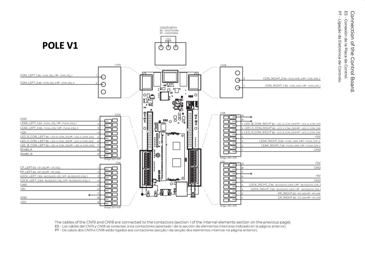
POLE V1 · green board
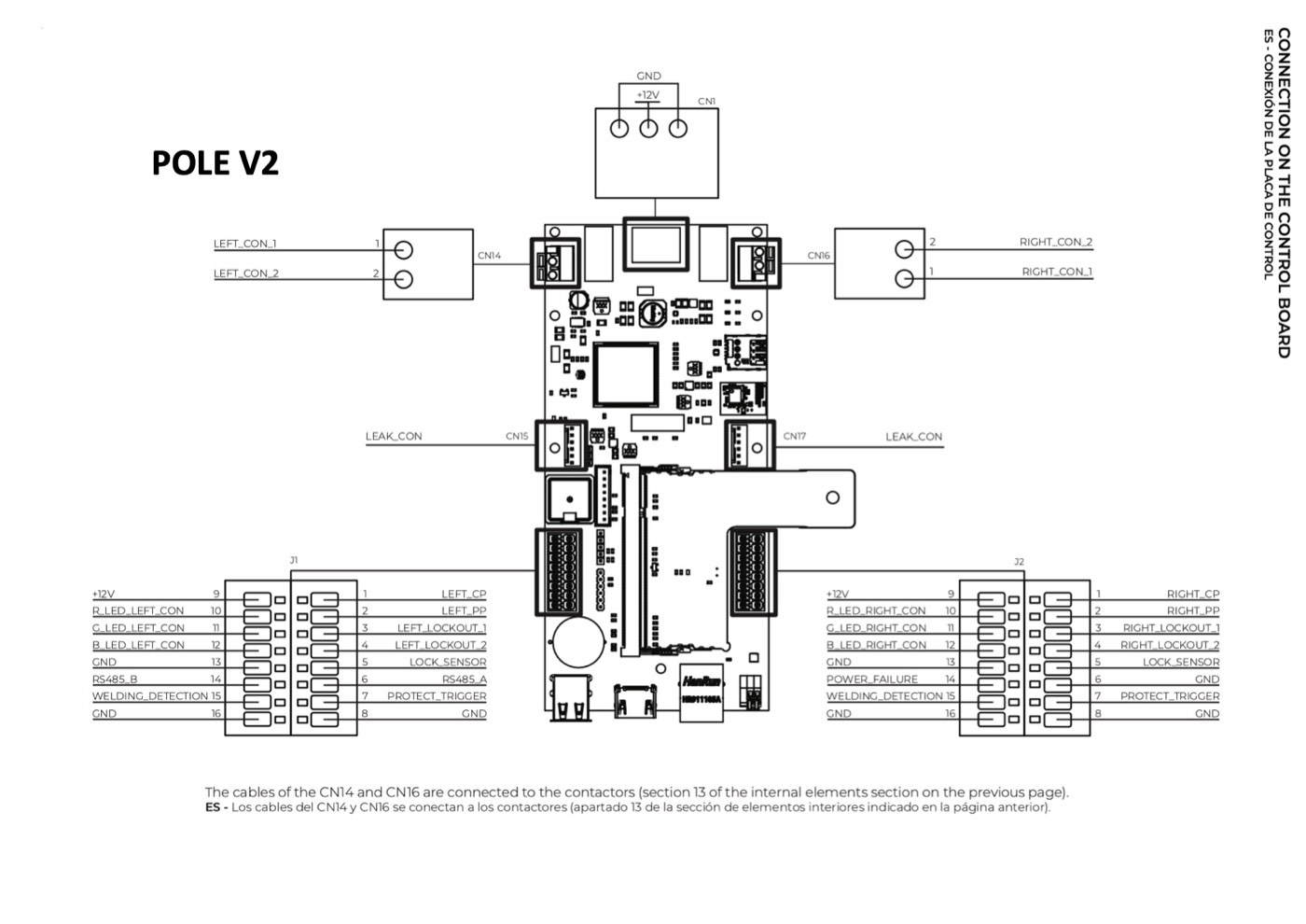
POLE V2 · white board
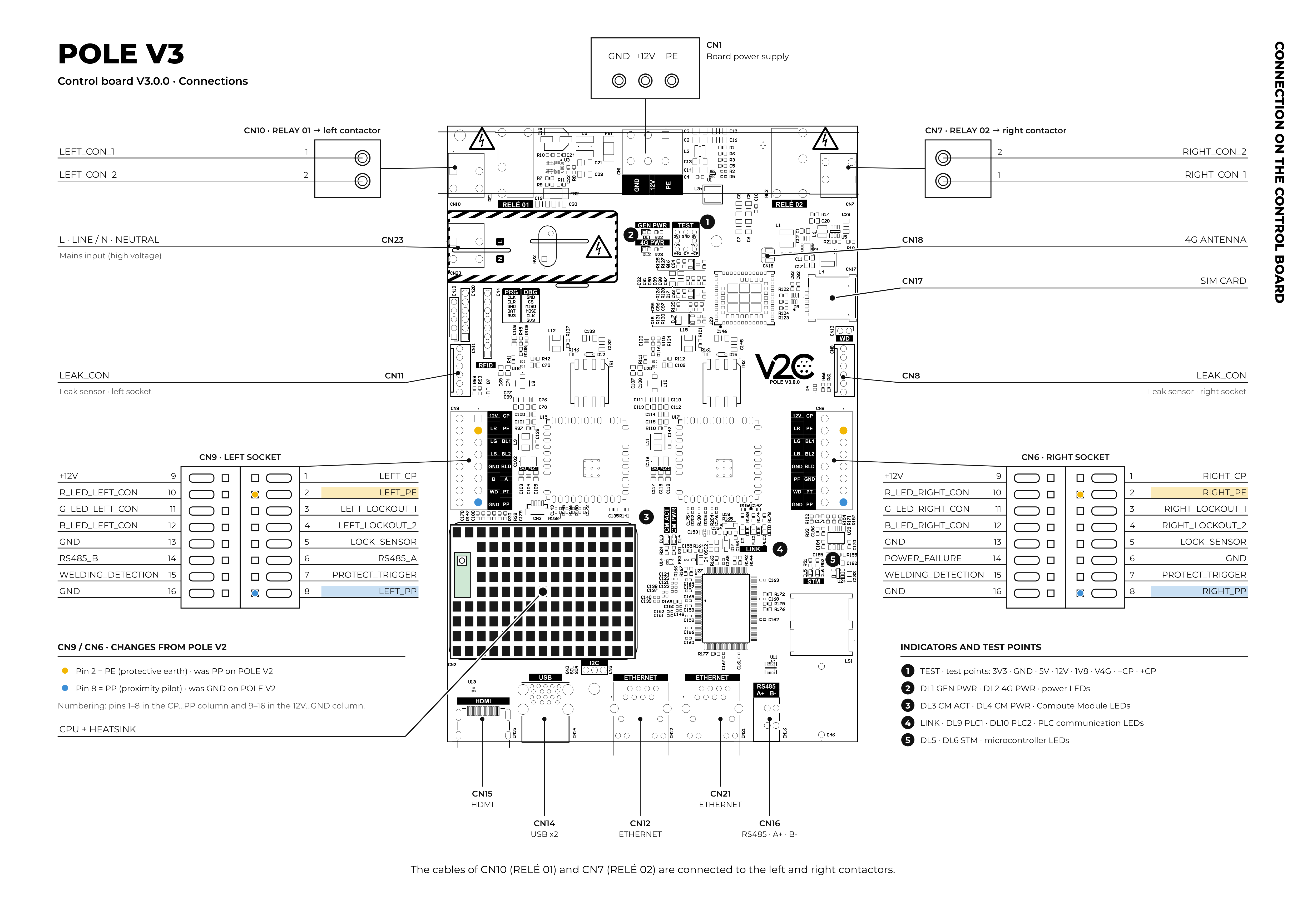
POLE V3 · white PLC board
Final checklist before closing
- Photos of the old board taken before disassembly
- All cables labelled with signal name
- Power supply connected to CN1
- Left and right contactors connected to their connector
- Left charging socket complete
- Right charging socket complete
- If the new board is V3: PP on pin 8 of both sockets
- Leakage sensors connected
- RS485 connected as confirmed with Technical Support
- +5V wires insulated and not connected
- No loose wires or exposed copper
- LED, locking and test charging on both sockets
If you need help from Technical Support
To help us assist you faster, have this information ready:
- Device serial number
- Version of the old and new board
- Photos of the old board and the new board connected
- Status of the LEDs and message shown in the app
Equipment for remote support
If you need help from the support team during the intervention, bring:
- Laptop with RJ45 (Ethernet) port
- USB data cable to connect your phone to the Pole
- If possible, a 4G router with two RJ45 ports to connect the Pole and the laptop
The 4G router allows the support team to connect remotely to the Pole and the laptop, and provide assistance while you are in front of the unit.
Need technical support?
Resolve your issue instantly via our AI Chat. If it is not resolved, submit a request in the Technical Support Center and we will contact you as soon as possible to offer you the best solution.